[Trade Journal]
Publication: Scientific American Supplement
New York, NY, United States
vol. 36, no. 921, p. 14715, col. 1-2
INSULATORS FOR HIGH VOLTAGE.
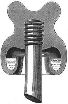
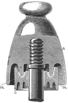
EXPERIENCE has shown that the best insulators for high voltage bare cables, carried on poles, are those in which surface leakage is prevented by a bath of highly insulating oil. There are various forms of these. One of the most common is shown in Fig. 1, and consists of a single-bell porcelain insulator, with the bell formed into an annular channel to hold the oil. This form is open to the objection that insects may weave their webs across the top of the oil channel, thereby reducing the insulation resistance to a very small figure when the webs are damp with rain or dew. The insulator used on the Tivoli-Rome high-pressure line is superior in this respect, since the on is quite inclosed. A diagram of this insulator is given in Fig. 2, in which A is an ordinary double-bell porcelain insulator and B is an adjustable insulator of the same material capable of carrying oil in an annular cavity, C. When the lower insulator is pushed up into its proper place, the inner bell of the upper insulator dips into the oil, as shown, and effectually prevents accumulations of foreign matter from short-circuiting it. The oil must be heavy and non-volatile. Resinous oils have been found to be the most serviceable. On this particular line, between Tivoli and Rome, there are four stranded copper cables, each 100 square millimeters in section and capable of carrying 130 amperes. The length of the line is 35 kilometers, and poles are arranged 38 meters apart. Each pole is 30 ft. high, and is constructed of wrought iron. There is a loss of 1,000 volts in transmission, the drop being from 5,000 volts at Tivoli to 4,000 at Rome.
 |
| Fig. 1. |
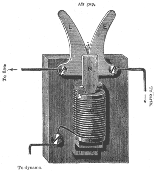
Special forms of lighting guards are necessary on all overhead lines which are worked at high voltage. Ordinary telegraph guards may suffice where the voltage is very low, but currents at high voltages would continuously arc from the line to earth through the ordinary guard when once the lightning has passed a spark between the two. The principle of all such guards is that the ordinary pressure of the line is not sufficient to pass a spark across the air gap which forms the guard, while the intense pressure of the lightning flash will prefer to establish a spark rather than face the high self-induction of the line and machines. The lightning, in passing across the air gap, volatilizes some of the metal of the electrodes, and thus enables a high pressure current to keep up an arc across the air gap which is sufficient to destroy the line. One of the most successful lightning guards for high-pressure lines is that
 |
| Fig. 2. |
invented by Prof. Thomson, of the Thomson-Houston Company. This is shown in Fig. 3, and consists of two curved metallic electrodes, L and E, which are so shaped and placed that there is a continually increasing air gap from the bottom to the top. The bottom of the air gap is placed between two elongated pole pieces of an electro-magnet, M, which is continuously excited by the current in the line. The connections are as shown in the diagram, one of these guards being placed in each line, between the line and the dynamo terminal. Whenever a flash of lightning strikes either the forward or return line, a spark is established between the metal electrodes, L and E, and will naturally, pass between the points where they are closest together. Being in a strong magnetic field, the spark is acted on by a repelling force, which drives it out of the field. But before the spark can have quite left the field between the pole pieces the distance across the air gap is too great for the line to keep up a current, so that the spark
 |
| Fig. 3. |
goes out — is blown out, in fact, by the magnetic field. When the line is not working, a lightning flash will simply pass across the gap, as in an ordinary guard, and no continuous arc will be established, so that the magnetic field is not required. The earthing wire must have a carrying capacity and mechanical strength equal to that of seven strand No. 16 galvanized iron wire, and should be attached to a metal plate buried in the ground at a depth of not less than three feet. The area of the earth plate must be at least four square feet. Instead of an earth plate, metallic pipes for water supply, if outside of buildings, may be used. — Electrical Review.
