[Trade Journal]
Publication: American Electrician
New York, NY, United States
vol. 10, no. 3, p. 97-100, col. 1-2
WATER-POWER LIGHT AND POWER PLANT FOR A SMALL TOWN.
DELTA LIGHT AND POWER PLANT.
BY S. H. DAILEY.
While the water power electrical generating plant described herewith is not one of large power, it is notable for excellent design and the efficient manner in which all of the local conditions have been met, both with respect to generation and distribution.
The town of Delta, which the plant supplies with light and power, is located in the extreme southeast corner of York County, Pennsylvania. The stream-Muddy Creek which supplies the power, drains the entire southeast section of York County, and even in the dryest season has a sufficient supply of water to furnish moo h.p. for a ten-hour daily run.
The power house is situated near what was at one time a natural waterfall of 20 ft., now covered by the dam.
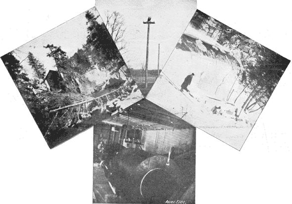 |
| Fig. 1. - Power House. Fig. 2. - Pole Line. Fig. 4. - Generating Room. Fig. 3. - View of Dam. |
Figs. 1 and 3 give a general view of the power house and dam. The location is an ideal one for the plant, having the advantage of bedrock for foundations of building and machinery, as also for an anchorage for the dam. At present, having only been in operation a few weeks, the power is being used in Delta for commercial and street lighting, running a pump for town water supply, furnishing power to a planning mill, printing office and other manufactures. As soon as the weather permits extension of the transmission lines, power will be furnished to the slate quarries in the vicinity, which are the largest roofing slate quarries in the country.
The dam is built on the crib pattern, being 35 ft. wide at the base, and 130 ft. at top, having a height of 41 ft. White and rock oak timber, 10 to 15 ins. square, securely pinned together with 7/8 in. square iron pins, is used for the cribbing, the foundation timbers being bolted to bedrock and those of the ends meeting solid rock, where they are firmly anchored. Fig. 3 shows the top of the dam.
The plan of the dam is that of a V of an angle of 160°, the apex of which points up stream. With the natural anchorage afforded it at the ends, there is, therefore, little fear of its ever giving any trouble. The down-stream section has a batter of 7 ft. The crib is closely packed with broken stone. The face is planked with 2-1/2 in. white oak, and to further prevent leakage these planks are covered with 1 in. boards, while beyond this is a filling of stone, gravel and earth, extending 30 ft. up stream and rising 45 ft. on the face of the dam. The top is covered with 3-1/2 in. oak plank, laid 1/2 in. apart to allow water to keep the cribbing wet.
In order that the water may be drawn oft at any time, there is a steel discharge pipe 4 ft. in diameter, with gate, placed hear the bottom, and running from back through the filling on the face. The storage capacity is estimated at 39,600,000 cubic ft. of water.
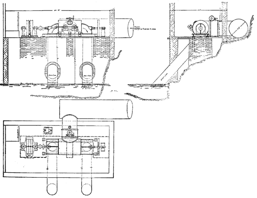 |
| Fig. 6. - Plan and Sections of Power House. |
The power house is 22 ft. by 44 ft, and is built of stone laid in Portland cement, and faced with the same inside and out. It is two stories high, the first or ground floor being in one room, and occupied by the power machinery and generator. A general view of the interior is given in Fig. 4. The second story is divided into store room and living apartments for employees. The foundations are laid on bedrock.
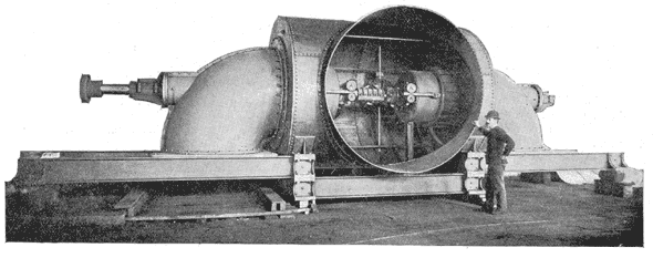 |
| Fig. 7. - Twin Turbine. |
The turbines, of which there are a pair, are of the McCormick type, as manufactured by S. Morgan Smith, of York, Pa. They are 24 ins. in diameter, and located one-half way between the surface of the water in the dam and the tail water, and with a 42 ft. head and 400 r.p.m., develop 575 h.p. As the general plan shows, the turbines are supplied with water from the dam, 250 ft. distant, by a steel tube 7 ft. 6 ins, in diameter, near the end of which, at right angle, is tapped a branch tube 6 ft. in diameter, leading direct to wheel casings. This 6 ft. tube is supplied with a gate valve in order that No. I wheel may be cut off from the supply pipe without affecting a second set of wheels, which will be installed at a later date. From the wheels the water is carried to the tail race by draft tubes 48 ins. in diameter. The efficiency of these wheels is rated by the makers at 85 per cent.
The speed of the turbines is regulated by a Replogle relay returning governor. This governor is purely mechanical in its operation and of the same type as used in the powerhouse of the Cliff Paper Company at Niagara Falls, where it has shown a governing efficiency of 2 per cent from full load to no load in particularly severe tests.
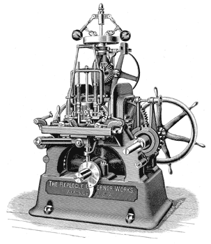 |
| Fig. 11. - Turbine Regulator. |
The generator was of the two-phase alternating current type, and was furnished by the Stanley manufacturing Company, of Pittsfield, Mass. It is designed to generate 350 k.w. at 5600 volts, with 800 alternations and a speed of 400 r.p.m. The generator is direct-connected to the shaft of the turbines by a flexible coupling. Fig. 10, showing the generator armature drawn out, gives a complete idea of the construction of the generator, showing, as it does, that simplicity and strength are striking characteristics-the wearing parts being only two journals. It has no moving wire, no collector rings and no commutator. The revolving part of the machine is really the field, but more properly termed the inductor. This is made of a steel casting, upon the periphery of which polar projections of iron laminae are securely fastened.
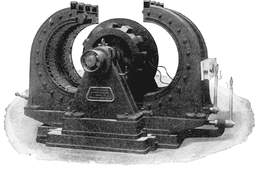 |
| Fig. 10. - Two-Phase Generator. |
The armature is made up of laminae of iron, and the individual coils, wound separately on forms, are secured in grooves provided for them in the laminations.
The armature and field wires are brought out from the machine to a terminal board (Fig. 9), consisting of two heavy slabs of marble fastened to the machine. Owing to the wide differences of loss in different lines and difficulty in balancing the load on different circuits, the E. M. F. of either of the two currents may be varied independently of each other by merely turning a handle at the terminal board one way or the other.
 |
| Fig. 9. - Generator Terminal Board. |
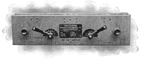
From this board the wires are led to the switchboard, which is of white marble and fitted with all the necessary switches, volt and ammeters, etc., a panel for each side of the machine.
The switches, current breakers, etc., are of a superior grade, and made absolutely safe for handling a current of such high voltage.
 |
| Fig. 12. - Static Ground Detector. |
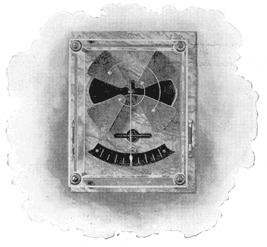
The static ground detector, Fig. 12, is used on this board, one on each side, and is fully described in AMERICAN ELECTRICIAN February, 1897. The exciter is of the multi-polar type. From the power house to substation No. 1 is five miles, this being the length of the transmission line completed; it will, however, be extended 1.75 miles, to sub-station No. 2, as soon as the weather permits.
 |
| Fig. 5. - Transmission Pole. |
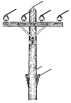
Chestnut poles are used, varying in length from 28 ft. to 40 ft., with a minimum diameter of 7 ins. at the top They are set 5 ft. in the ground, and all poles not in between poles in line is 100 ft., but at curves or at a turn, this distance is reduced, being 80 ft. in some cases and 90 ft. in others.
The cross-arms are of yellow pine, 5 ft. x 4-1/4 in. x 3-1/4 in., with locust pins, carrying, four No. 4 B. & S. gage soft-drawn copper wires, 18 ins. apart, one phase on each side of the pole. The cross-arm is let into a gain, 1 in. deep, and held there by two 7 in. x 1/2 in. galvanized lag bolts, the bolt being screwed in-not driven. To further support the arm, a pair of. galvanized iron braces, 1-1/2 in. x 1/4 in. x 19 in., are bolted to it by 3/8 in. bolts, and toed to pole with one 3 in. x 1/2 in. lag bolt. The gain for a second cross-arm was cut at the time of construction, to be utilized when the plant is extended.
One transposition is made in the line about one-half way between the power house and the point of distribution.
The insulators, which were furnished by R. Thomas & Sons Company, East Liverpool, O., are of the triple petticoat type, 5 ins. in diameter, 5 ins. high, and weigh 5 lbs. each. The glazed surface between the pin and the wire is 11-1/2 ins. All were subjected to a break-down test of 40,000 volts.
A barbed wire, strapped and stapled to the peak of the pole, is run the entire length of the line, and grounded at the butt of a pole every half-mile.
Six feet below the transmission line is run a private telephone line, connecting the sub-stations and power house. This line, which has a transposition every half mile, is also arranged to connect with the local telephone system when desired. The drop in the transmission line is to per cent.
Fig. 8 shows the manner in which power and light are distributed. At present there are in sub-station No. I-located about the centre of Delta-three step-down transformers. Two are of 35 k.w., converting from 5000 volts to 450 volts, one on each phase, and supply power to manufacturers by four No. 2 B. & S. soft-drawn copper wires, constituting the main power line. From these feed wires are led two motors, of a size depending upon the power supplied. The other transformer is of 40 k.w., converting from 5000 to 1200 volts, and supplying current to a switchboard, which is in the same station, for the Delta Electric Light Company, a separate corporation, under whose supervision the commercial and street lights are managed.
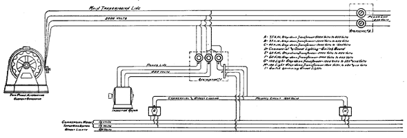 |
| Fig. 8. - Diagram of Circuits. |
It will be noticed that the 40 k.w. transformer is attached to one phase only. The danger of overbalancing the system by so doing is governed at the terminal board on the generator. From the sub-station switchboard two No. 8 B. & S. insulated wires are run to four transformers of 100 lights capacity each, converting from 1200 to 220 and 110 volts, and placed upon the poles at such positions as to feed the main lighting circuit evenly.
The town line consists of six wires, and is run on two cross-arms, one two-pin arm on top carrying the primary circuit, and a four-pin arm below, which carries the secondary circuit of three wires for commercial service, and one for the street lights. The street lights, as shown in Fig. 8, are connected on the outside wire and one leg, of the three-wire system, thus being on a 220-volt circuit, which is run to the switchboard and there controlled by an automatic switch, which shuts off the current at midnight.
In sub-station No. 2 will be placed, at first, two 60 k.w. step-down transformers, converting from 5000 volts to 450 volts, which will furnish power to slate quarries, each of which will a 30 k.w. machine for hoisting, cutting and dressing slate.
This plant to-day is working in first-class order, and will prove, in a short time a good investment to the owners, the Delta Power Company. As soon as 400 h.p. of the present installment are contracted for, it is the company's intention to duplicate the present machines.
