[Trade Journal]
Publication: American Electrician
New York, NY, United States
vol. 10, no. 4, p. 135-140, col. 1-3,1-2
THE DOLGEVILLE (N. Y.) WATER-POWER ELECTRIC LIGHT AND
POWER PLANT.
BY E. A. GRISSINGER
ANOTHER substantial impetus was given to the generation of electrical energy through the medium of water power, when on Jan. 15 of'the current year the Dolgeville Electric Light & Power Company put in operation its excellent and modern plant at High Falls, N. Y., on what is now known as the Auskerada River. That the opening day had been looked forward to for a long time was evidenced by the large number of people present on the occasion. Through the columns of other papers, the social and literary character of the gathering, subsequent banquet, etc., furnished interesting reading; and the purpose of this paper is to deal more particularly with the organization of, and certain technical details relating to, the installation.
The Dolgeville Electric Light & Power Company was organized and incorporated in December, 1891. The capital stock was fixed at $25,000. Early in 1892 some direct-current apparatus was installed, furnishing light and power in small units. This plant has always been operated by water power under 22 ft. of head. The calls upon the company for electrical energy expanded to such an extent that, previous to the opening of the new power, the company was operating the following machines: Two 50-k.w., 500-volt, direct current; one 90-k.w., 500-volt, direct current; two 45-k.w., 110-volt, direct current; 20-k.w., 110-volt, direct current of General Electric make; and one 7-kw., direct current, type "Z," Edison generator, bearing the date of 1879 and numbered "No. 2."
| |||
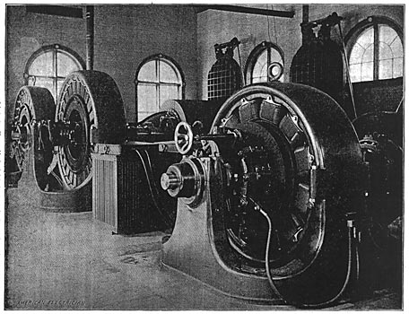
| Fig. 1. General View of the Plant. |
The machines of 110-volt potential furnished current for the commercial lighting circuits. Those of 500 volts were for power purposes, and also furnished current for street lighting. The latter was accomplished by clusters of five lamps in series across the 500-volt mains. About forty such clusters were in use.
One pair of 35-in. horizontal Victor turbines, running at 168 r.p.m., and developing 480 h. p. under 22 ft. of head, furnished the power necessary to operate the plant.
| |||
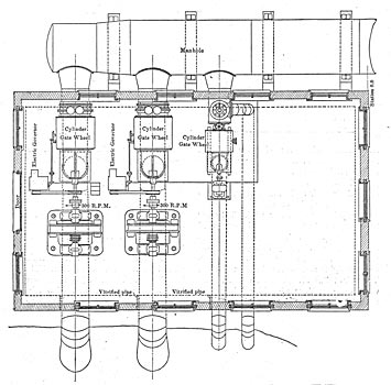
| Fig. 2. Plan of Power House. |
The business of the company had outgrown its narrow confines. The directors were thoroughly appreciative of rapid strides made in the field of power transmission, and recognizing their own peculiar and great advantages for water power development, decided early last year to increase the capital stock of the company and proceed with development on a modern scale. Accordingly a contract was made in the early spring with the Stilwell-Bierce & Smith-Vaile Company for the hydraulic development, which company supplied all plans and built the plant complete up to the generators, Mr. A. C. Rice, general superintendent and engineer of the company, being in direct charge of the work. In July a contract was made with the Westinghouse Electric & Manufacturing Company for the electrical equipment.
| |||
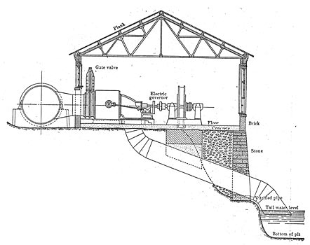
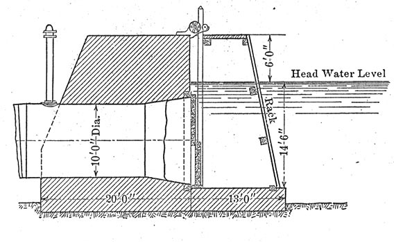
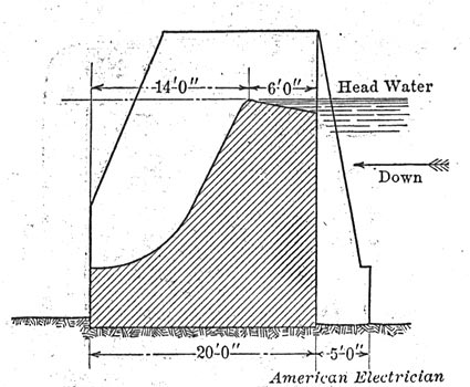
| Fig. 3. Cross-Section of Power House. |
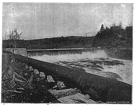
The Dam and Flume. As soon as the weather permitted it, work was begun on the construction of the dam. This is a good example of masonry construction. The height at the spillway is 20 ft., and each abutment 6 ft. higher, the total length being about 105 ft. The width at the top is 7 ft., and at the bottom 26 ft. The up-stream side of the dam is perpendicular, the down-stream side affording a good apron, the lower curve drawn to a radius of 10 ft. Limestone was used in the construction, the face stones coming from Ingham's Mills, 2 miles below the power site. The Glens Falls Portland Cement Company furnished the cement, which was their Victor brand. In mixing for use, one part was used with four parts of sand. Fig. 5 is a view of the dam, and Figs. 10, 11 and 12 show sections through the head gate, waste gate and main portion, respectively.
| |||
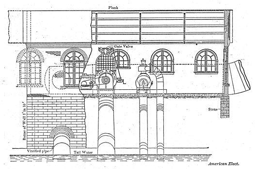
| Fig. 4. Partial Longitudinal Section and Side Elevation of Power House. |
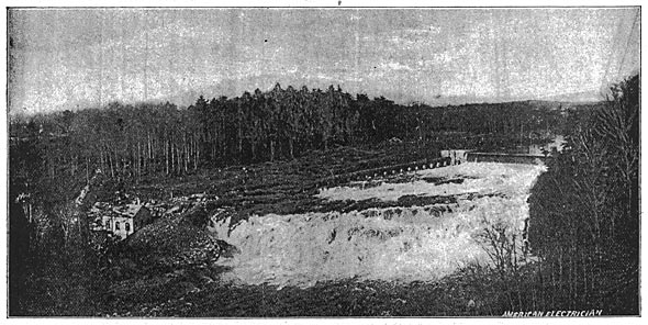
The westerly abutment contains a flush gate 4 ft. x 6 ft., to which is attached one set of No. 6 waste gate irons for operating the same. Beside this waste gate is the head gate, 12 ft. square in two sections, being fitted with a pass gate to relieve the pressure when filling the flume. These gates are operated with two sets of No. 2 head gate irons, as made by the Stilwell-Bierce Company. The steel flume extends from the head gate to the power house, 520 ft. away. This flume is 10 ft. in diameter, and is made of 1/4-in. steel plate, all longitudinal seams being double riveted. Just outside the dam is a vent pipe, which will assist toward relieving the flume from any sudden strains. Masonry piers at intervals of 20 ft. furnish the necessary supports for the flume. The latter has two curves in its descent to the power house level, and was made of sufficient diameter to provide for the ultimate development of this plant. The flume terminates in the customary steel forebay used in connection with horizontal wheels, Fig. 6 gives a general view of the dam, steel flume and power house.
The Power House. The power house is of brick construction, with its foundations and those of the machinery carried to bed rock. The building is 46 ft. x 64 ft, x 16 ft. to the roof trusses, which latter are of steel construction, four in number. The draught tubes from the wheels are arched over with substantial masonry arches, and the filling about these and the foundations of the machinery consists of broken stone and hydraulic cement. The whole is topped with a 6-in. layer of concrete, constituting the finished floor of the building. Telephone communication extends from the station to the village, and will have connections ultimately to all points where the power will be used. Fig. 2 is a plan of the building, showing the arrangement of the machinery. The switchboard has been placed at the right end of the building toward the dam. The power house is so situated and the excavations have been proceeded with in such a way as to permit of extensions longitudinally to the capacity of the plant, which will ultimately be 3600 h.p. From Fig. 3, showing a cross section of the station, it will be noted that the steel forebay is placed just outside and parallel to the building, extending the, full length of same. Fig. 4 shows a partial longitudinal section and side elevation of the power house.
| |||
| Fig. 5. View of Dam and Flume. |
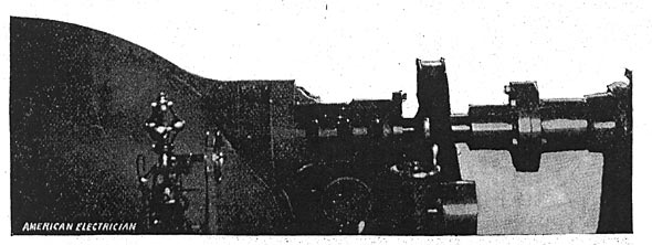
Hydraulic Equipment. There are two 36-in. horizontal Victor turbines, each direct connected to one 450-k.w. two-phase Westinghouse generator. Each of these wheels will develop 600 h.p. at 300 r.p.m., under the working head of the water, which is 72 ft. They are mounted in cylindrical steel casings, discharging at the end downward through draught tubes, which latter, passing through the power house foundation, extend a few inches below the surface of tail water. Each wheel is supplied with a Giesler electro-mechanical governor, which gives satisfactory regulation. One of the wheels, with governor in the foreground, is shown in Fig. 7. One exciter wheel, 15 ins. in diameter, has been installed, running at 375 r.p.m and driving a 15-k.w., 110-volt multipolar exciter. As the load upon the exciter is approximately constant, no governing mechanism has been deemed essential. The gates at the larger wheels are operated through the medium of a double set of bevel gears and of the exciter wheel by means of an ordinary hard wheel. All of the turbines are of the cylinder gate pattern, the two larger ones being "Victor Specials."
From the supply main to the exciter wheel a relief pipe is tapped, which, by means of a suitable valve arrangement, permits of water being drawn from the flume when such procedure is deemed essential. The turbines run right-handed. The speed of the driving mechanism at the governors is 483 r.p.m. All of the construction pertaining to the hydraulic equipment is substantial and well made.
| |||
| Fig. 6. General View of Dam, Flume and Power House. |
The Electric Equipment. Fig. 1 gives a general view of all generators except the exciter. In the foreground will be noticed the rotary transformer of 250 k.w. capacity, to the left of which are two 450-k.w., two-phase alternating current Westinghouse generators, direct connected to the turbines by face couplings. The generators are of 2400 volts potential, and will deliver their rated output at 300 r.p.m. at 94 per cent efficiency under continuous service of any nature, no part showing a rise in temperature of more than 40 deg. C. above that of the surrounding atmosphere. The armatures are of the slotted type, wire wound; the frequency is 60 cycles, there being twenty-four poles.
| |||
| Fig. 7. One of the Turbines. |
The field frames are cast from a special grade of iron, insuring high permeability. They present the usual characteristic of Westinghouse apparatus that of beauty and symmetry in design. Laminated poles are used, insuring high efficiency close regulation and cool running under trying conditions of service. The bearings are of liberal proportions, self-oiling, there being two oil rings to the bearing. The fields divide through the center in a horizontal plane, such being necessary in the direct-connected type of generator.
The armature core consists of a cast steel spider, having upon its periphery a number of projections, which are turned off to the proper radius, after which operation they are centered and carefully dovetailed upon a machine suitable for the purpose. The armature stampings, which are of specially annealed, steel, are then manually built up on this spider, their projections fitting into the slots, dovetailed fashion. When the proper number of laminae are obtained, they are forced in closer relation by pressure, and so retained by means of steel rings fastened together from each side of the core. Four collector rings are provided, which convey the current to the brushes, 93.7 amps. being the normal current per phase.
| |||
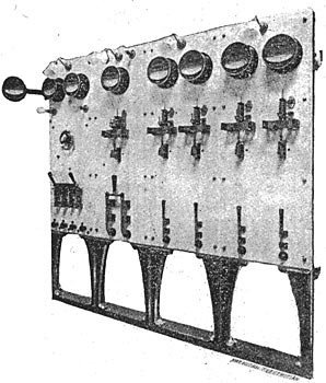
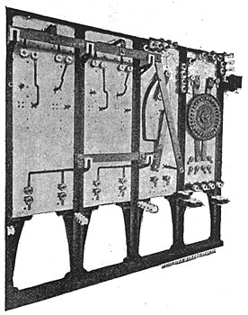
| Fig. 8. Four Panels of Station Switchboard. |
Four No. 1 wires carry the current from each alternator to the switchboard, and No. 4 wires convey the exciting current between switchboard, exciter and alternators.
The generators are securely fastened to the foundations by means of anchor bolts provided for the purpose, and are designed with such a factor of safety that they will withstand a speed equal to that of the wheels when traveling at the spouting velocity of the water under 72 ft. of head.
In view of the fact that there were a large number of direct current motors in use in Dolgeville, it was found necessary to provide a 250-k.w. rotary transformer. This machine delivers direct current at 600 volts potential, running as an alternating current motor, self excited, the fields having a compound winding. The speed of this machine is 600 r.p.m. On the direct current side there are twelve brush holder arms, two carbons to the arm. The carbon holders are of the swivel type, being a late design of the Westinghouse Company. The rocker arm is readily adjustable by means of a worm and bevel gear, which device renders the movement self-locking.
Bar winding is used on the armature, and is of the same general type as is found on the Westinghouse railway generators. The open type of winding and apertures in the armature core insure excellent ventilation.
For the purpose of starting the rotary and bringing it up to speed, a two-phase type "C" induction motor of the same general design as those largely in use at Buffalo and Niagara Falls, has its rotating secondary keyed to the shaft of the rotary. The primary of this motor rests upon a bracket fastened to the frame. Current for the induction motor and also for the alternating current end of the rotary is obtained from the alternators through a pair of static transformers, each of 125 k.w. capacity. These converters are the self-cooling oil type, and receive current at 2400 volts, transforming to any one of three e.m.fs., 405, 430 or 455. By this means any change in the direct-current power circuit by virtue of increased or decreased load can be met.
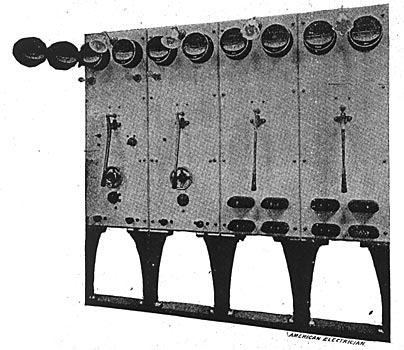
Fig. 8 shows four panels of the station switchboard. The two panels at the left control the alternating current generators. Each panel is of Vermont marble, 65 ins. x 24 ins. x 2 ins. resting upon cast iron standards. Upon each generator panel is mounted a pair of ammeters of the round pattern, a pilot lamp, two field plugs, a four-pole, double-break plunger type switch and voltmeter receptacle. Panel No. 1 contains in addition one combination A. C. & D. C. rheostat, ground detector receptacle and push with lamps; panel No. 2 has synchronizing lamps and A. C. rheostat, the switchboard having been designed to operate the generators in multiple. Upon a swinging bracket to the side, one voltmeter for each generator is mounted. These are also of the round pattern, and have a range of 0 to 140 volts.
| |||
| Fig. 10. Section Through Head Gate. |
The feeder panels, of which there are two, each contain a pilot lamp, four-pole double-break, plunger type switch, four lignum vitae fuse blocks, using aluminum fuses, and two ammeters of the round pattern. Special attention is called to this board on account of its neat appearance, simplicity tor alternating current work, and the tact that there are no metal parts on its face which can be charged in any way by the current handled by it. The combination rheostat controls the exciter voltage and also the fields of the alternating current generator. The exciter rheostat is mounted directly on the back of the board, while the face plate only of the A. C. rheostat is so mounted while the rheostat proper stands upon the floor back of the board. This auxiliary piece of apparatus is of the ironclad type, built up of columns consisting of iron ribbon wound in coils with mica between the layers, each coil so formed having its own terminals admitting of any combination in series or parallel.
| |||
| Fig. 11. Section Through Waste Gate. |
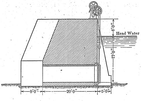
Fig. 9 gives a rear view of the A. C. panels, showing the method of supporting the conductors. At the top of the board are the converters for use with the voltmeters and ground detectors.
The plunger type switch shows eight terminals. These are accounted for by the fact that the switch is four-pole, with two terminals or plunger receptacles connected in series in each leg of the two-phase circuit, making it a double-break switch. The breaking of a circuit in such a form of switch is caused by the arc blowing itself out through an aperture provided in the airtight chamber within which the plungers work. This type of switch, as perfected by the Westinghouse Company, successfully breaks its circuit when fully loaded, even though there be a heavy lagging current. They have added much in the way of facilities for handling power circuits using an alternating current.
| |||
| Fig. 12. Section Throuogh Body of Dam. |
Figs. 13 and 14 give a good idea of the front and rear of the direct-current board. This board is a continuation of the alternating current panels, each panel being of the same size. The first panel to the left is for controlling the rotary transformer. At the bottom of this panel are four plugs for throwing in the induction motor, thereby starting the rotary. Two lamps upon this panel indicate when the machine is at synchronous speed, at which time the four-pole quick-break switch is thrown, and the plugs withdrawn, relieving the small motor, which remains out of circuit. The hand wheel operates the field rheostat of the rotary. Two A. C. ammeters and a swinging D. C. voltmeter complete the rotary panel.
| |||
| Fig. 13. Front of Direct Current Switchboard. |
The second panel is the load panel for the D. C. end of the rotary, containing a double pole switch, circuit breaker and ammeter. The last two sections of this board represent feeder panels, each of two circuits of 200 amps. capacity. At present these feeder panels supply current to three independent circuits, each circuit of No. 0 wire. All leads between the switchboard, dynamo and transformers are carried beneath the floor in a brick lined conduit of ample size. They are supported upon porcelain insulators, attached to wooden cross-pieces, which latter are placed at intervals of 3 ft. This conduit will be covered with a glass plate 1 in. in thickness and extending its entire length, thus keeping in view at all times the wiring of the circuits.
As previously stated, the original plant supplied current at no volts for commercial lighting. This system is now abandoned, and with some changes in the wiring, together with the necessary transformers, the A. C. generators are doing that work. One of the A. C. feeder panels is used for the purpose of controlling the lighting circuits. The remaining A. C. feeder panel will be used tor the circuit going to the step-up transformers which will supply current to the transmission line tor use in Little Falls.
| |||
| Fig. 14. Rear of Direct Current Switchboard. |
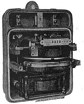
For the commercial lighting and power work, the Dolgeville Company has adopted the Shallenberger wattmeter. This meter is shown uncovered in Fig. 15. It measures energy in kilowatt hours, and is inclosed in a substantial metallic case, which prevents injury and tampering. On account of the fact that the torque of such a meter is directly proportional to the power passing, one of these meters will start on less than one-half of 1 per cent of its rated load, and no amount of induction can affect the accuracy of the readings. No constants are used in calculating the energy registered, inasmuch as it reads direct.
At present the plant is furnishing current for about 2000 lights and 350 h.p. in motors, and is reported to be working in excellent fashion.
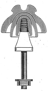
The Transmission Line. This will be 8 miles in length, extending from the power house to Little Falls, N. Y. The poles are 25-ft. cedars, with 7-in. top, furnished by the Kerby Dennis Company, of Marinette, Wis. They have already been set, numbering fifty to the mile. There will be one cross-arm per pole of yellow pine, 8 ft. x 4-1/4 ins. x 3-1/4 ins., well braced. No. 4 hard-drawn copper bare wire will be strung upon porcelain insulators and pins furnished by Mr. Fred M. Locke. This insulator is 5-1/4 ins. in diameter, and made from three shells of vitrified china fused together with glaze, thus affording a solid insulator of the strongest kind, both electrically and mechanically. The pin is 1/2-in. steel with a locust top boiled in paraffine, and a porcelain base. By the use of these an arc or static discharge will not burn them off. The sleet and moisture repelling character of insulator and pin when carrying current is therefore carried down to the cross arm; and it is estimated that the arcing distance is increased thereby, corresponding to an increase of 10,000 volts in potential.
| |||
| Fig. 16. High Voltage Insulator. |
The line will carry 600 h.p. at present, at a potential of 10,000 volts, secured by means of two Westinghouse self-cooling oil type converters, which receive current at 2400 volts, two-phase, and transform to 10,000 volts, three-phase, this method of being known as the Scott method of transmission. At Little Falls will be installed two Westinghouse lowering converters, which will receive the current at 9500 volts, three-phase, and transform to 2200, two-phase, ready for distribution for power purposes. The converters mentioned have an efficiency of 98-1/2 per cent.
The transmission line will be transposed three times between the power house and Little Falls, so that each leg of the three-wire circuit will be on the same side of the line for one-third of the distance. No telephone line will be strung on the poles of the transmission line, as one already exists on a separate line running on the opposite side of the railroad. It should also be noted that the high tension line follows the tracks of the Little Falls & Dolgeville Railroad almost the entire distance.
| |||
| Fig. 15. Shallenberger Watt Meter. |
For lightning protection the high tension circuit will be provided with Wurts lightning arresters, three being placed at each end of the line, one for each leg of the circuit. These are of an improved pattern, as manufactured by the Westinghouse Company for transmission work at high potentials. They are each mounted in a rack resting upon glass insulators and provided with choke coils. The loss in the line at full load will be 5 per cent.
In General. The hydraulic part of the plant was designed by Mr. A. C. Rice, superintendent and chief engineer of the Stilwell-Bierce & Smith-Vaile Company, of Dayton, Ohio. The electrical part of of the work was laid out by the writer.
The Dolgeville Electric Light & Power Company have absolute control of the High Falls water power, and nominal control of rights whith will enable it to develop and market 17,000 additional h.p. The facilities for storage are of the best. The headwaters of the Auskerada form a perfect network of lakes, whose area will aggregate 10,000 acres, which is ample for the complete utilization of 20,000 h.p. The natural drainage of the stream through a thickly wooded country above Dolgeville is 260 square miles.
Within the limits of 2 1/2 miles above Dolgeville, and 2 1/2 miles below, the stream has a fall of 412 feet, which is divided up into eight different power sites. A plant immediately below the present installation will obtain 84 ft. of head, and next below 65 ft. The situations are ideal for cheap developments.
The Little Falls market for power is a good one, and there are others not very far away, to which will be sent in the near future power from the Auskerada. Already Little Falls has observed the value of electric power, and subscribed for 300 h.p., which will soon be ready for use.
The officers of the Dolgeville Company are, E. R. Wanckel, president; N. A. Snell, secretary; W. S. Armstrong, treasurer; Alfred Dolge, W. S. Armstrong, N. A. Snell, executive committee.
