[Trade Journal]
Publication: American Electrician
New York, NY, United States
vol. 10, no. 12, p. 527-532, col. 1-2
LONG DISTANCE ELECTRICAL TRANSMISSION OF STEAM POWER.
THE PLANT OF THE COLORADO ELECTRIC POWER COMPANY.
BY RALPH D. MERSHON.
THE Cripple Creek mining district, though not far from some of the best coal fields of Colorado, is about 5000 ft. higher than the most accessible of them. This lift of 5000 ft., making itself felt through the medium of freight rates, means high-priced fuel, and, in consequence, steam power is expensive, especially in the case of such intermittent work as hoisting, which constitutes the major portion of the work done in the mines. Another condition contributing toward a high average cost of power is the existence of numerous small users, for, although the large mines of the district consume much power, both for steady and intermittent work, there are many small mines and prospects whose aggregate power consumption equals or exceeds that of the large mines. For these reasons, in addition to the fact that many of the mines operate continuously, the Cripple Creek district furnishes a market especially favorable to the profitable transmission and distribution of power by electricity. Recognizing this fact, the late O. B. Shallenberger, of Rochester, Pa., and D. V. Donaldson, of Colorado Springs, undertook in the summer of 1897 the formation of the Colorado Electric Power Company, a company whose primary object was to supply power to "the greatest gold camp in the world." The brilliant reputation of the former of these men in electrical work and the confidence reposed in the latter by all who knew him, made the floating of the enterprise easier than is usually the case with such ventures, and in the fall of 1897 work was begun on a transmission plant which has now been in operation for some months, and which is one of the most complete of its kind in this country.
 |
| Fig. 1. - Views of the Line Construction. |
After careful consideration of water power for this work it had been decided that, in view of the existing irrigation rights on the streams within reach of the market and the large reservoirs which would be necessary in order not to interfere with these rights. it would be cheaper to generate power by steam than by water. A site for the power station was therefore chosen at Canon City, Colo., a point offering many advantages for the economical generation of power, chief among which is its nearness to the coal fields.
The station is located so as to be accessible from both of the railroads entering Canon City; coal can be delivered from either of them on to a side track and unloaded thence directly into the coal bunkers. It is near the Arkansas River, from which water is taken for condensing purposes, and, if it should become necessary, coal may be delivered to it by a downhill wagon haul from the mines owned by the company.
The building is a substantial structure of brick and steel, and at present represents just half of what the completed structure will be, as both the building and equipment have been laid out with a view to an increase of capacity when business shall demand it, the increase to be made without interfering in any way with the operation of the plant. The general arrangement and dimensions of the building are shown in the ground plan, Fig. 2.
 |
| Fig. 2. - Ground Plan of Power House. |
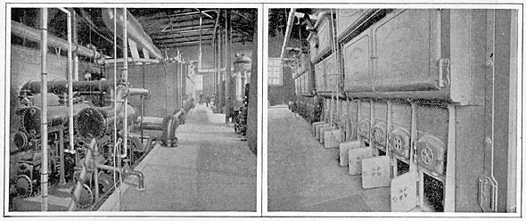
The fire-room equipment, shown in Figs. 3 and 4, consists of a battery of Heine water-tube boilers, manufactured by the Heine Safety Boiler Company, of St. Louis; the condensing apparatus, consisting of surface condensers with combined air and circulating pumps, made by the Snow Steam Pump Works, of Buffalo, N. Y.; Snow feed pumps; Wainwright corrugated tube heaters, made by the Taunton Locomotive Manufacturing Company, Taunton, Mass. The boilers, pumps and condensers have such a capacity and are so arranged that one unit is always idle as a reserve in case of emergency. The stack is of steel, guyed, and resting upon a substantial brick base. The water supply for the surface condensers is taken from the Arkansas River at a point about 400 feet above the station, and is brought by a wooden flume to the settling tank, whence it is drawn by the circulating pumps, sent through the condensers and discharged again into the river.
| |||
| Fig. 3. - Combined Air and Circulation Pumps. Fig. 4. - the Boiler Plant. |
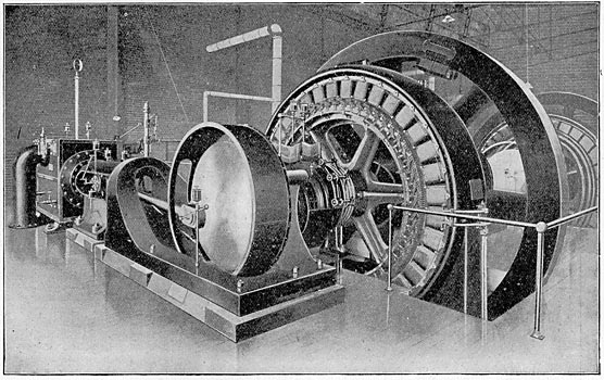
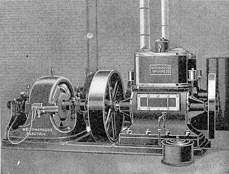
The steam equipment of the engine room consists of the three main engines, and two exciter engines. The main engines are Hamilton-Corliss cross compound condensing engines, with receiver and reheating coil, made by the Hooven, Owens & Rentschler Company, Hamilton, Ohio, They take steam at 125 lbs., and their speed is 100 r.p.m. Though they normally run condensing they may be run non-condensing in case of emergency, and will carry their load under those conditions. Each one is direct connected to a Westinghouse three-phase generator delivering current at 500 volts and 3600 alternations per minute, 30 cycles per second. The exciter engines are Westinghouse "Standard," running at 350 r.p.m. They take steam at the same pressure as the main engines and exhaust into the heaters, as do also the pumps in the fireroom. Each exciter engine is connected by means of a spring coupling to a Westinghouse 125-volt direct-current dynamo. Either of the exciter rigs is capable of exciting all of the main generators. The nominal rating of the main generators is 470 k.w each, but the specifications on them and the engines were such that the three generating units are together capable of delivering something over 2000 h.p. In operation, one of the main generators will be kept idle as an emergency reserve.
| |||
| Fig. 5. - One of the Main Units. |
| |||
| Fig. 6. - An Exciter Set. |
The current from the main generators and exciters is carried by cables in tunnels under the station floor, each to its own switchboard. The exciter switchboard is of the Westinghouse standard type, consisting of two marble panels-one for each exciter-on which are mounted the usual instruments and switches. The main switchboard has four panels-three generator panels and one load panel. Each generator panel has besides the usual field plugs, rheostat and main switch, three ammeters, one for each machine lead, and two Shallenberger indicating wattmeters, the sum of whose reading gives the output of the generator.
| |||
| Fig. 7. - the Switchboards. |
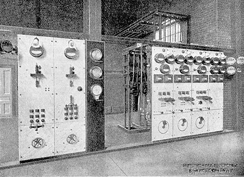
The load panel has three ammeters and two wattmeters. The sum of the wattmeter readings is the total output of the bus bars. The ammeters, however, do not indicate the bus bar currents; each measures the current to one of the three step-up transformers, and is thus a ready means of detecting and locating any incipient trouble in the transformers or any unbalancing of the load. The additional instruments are three voltmeters and a synchroscope mounted as an arm at one end of the board so as to be visible from each panel. The synchroscope can by means of plugs be used for synchronizing any machine with the bus bars. One of the voltmeters can be plugged on to any phase of any machine.
| |||
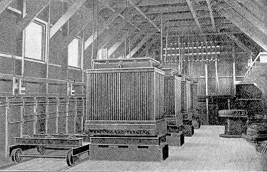
| Fig. 8. - Step-Down Transformers and Trucks for Handling. |
Of the remaining two voltmeters one at all times indicates the voltage of the bus bars; the other in connection with a compensator indicates at all times the voltage on the secondary distribution circuits at Cripple Creek, and thus enables the station attendant to hold the distribution voltage at any desired value.
None of the instruments on the board carry the main current; they receive current from the secondaries of series transformers, whose primaries are in the main leads. These series transformers are mounted upon a rack behind the switchboard. As will be seen from the illustrations, there has been left between the main switchboard and the exciter board a space for additional panels, when the plant shall be extended. Mounted upon a mahogany panel, which will form a part of the completed switchboard, are a steam gage, vacuum gage and recording pressure gage, this arrangement bringing the operation of both the steam and electrical machinery under observation at one place.
| |||
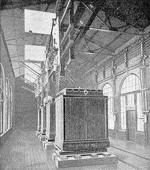
| Fig. 9. - Step-Up Transformer Bank at Station. |
 |
| Fig. 10. - Wattmeter Connections. |
The connections of the wattmeters are shown in Fig. 10. 1, 2 and 3 may represent either the three bus-bars or the three leads of any machine. A and B are the two indicating wattmeters. S, S, S, are series transformers, each included in one of the three leads. C is a single coil shunt transformer having a terminal brought out at its middle point. As will be seen from the diagram, the wattmeter, A, receives the current for its series coil from the series transformer in the lead, 1, while its voltage coil is connected from lead No. 1 to the middle point of the single coil transformer C. Wattmeter B receives for its series coil a current which is a resultant obtained from the two series transformers in leads 2 and 3. Its voltage coil is connected between the leads 2 and 3.
From the switchboard the current goes overhead to the step-up transformer house. The cables carrying it are brought down along the wall of this building to the transformer switches, which are mounted upon the wall opposite their respective transformers. From the switches cables go under the floor to the transformer foundations and pass up through them to the transformers.
The step-up transformers are four in number, one being always idle as a reserve. They are the Westinghouse self cooling oil transformers, the tanks containing them being made of sheet iron and with a number of corrugations for obtaining the necessary radiating surface. They raise the voltage from 500 to 21,000 volts. Both the high and low-voltage coils of the three transformers in service are connected in delta, so that one transformer may at any time be cut out without interfering with the running of the plant. This allows a damaged transformer to be replaced by the reserve transformer without interrupting the, service, an advantage which the Y-system of connection lacks. The arrangements for throwing in the relay to replace one of the transformers in service are simple, and such that the substitution can be made in a few minutes. It is accomplished on the low-voltage side by means of a pair of relay cables and double throw, double pole switches for each of the three transformers normally in service; on the high-voltage side by means of double pole circuit breakers, of which-there is one for each transformer, and long-handled plugs, by means of which the relay is plugged onto the proper pair of 20,000-volt bus bars.
In addition to a hand-tripping device the high-voltage circuit breakers are arranged; to open automatically whenever energy passes through them in the wrong direction; that is, whenever a transformer becomes disabled its circuit-breaker will disconnect it from the 20,000 volt bus bars. Any trouble in a transformer which will cause its high-voltage circuit breaker to open will also blow the fuses in its low-voltage leads. The result is that a damaged transformer is automatically cut out. Two of the raising transformers are capable of carrying the full output of the station indefinitely, so that as far as continuity of service is concerned there is a reserve transformer capacity of 100 percent.
From the 20,000-volt terminals of the transformer the current is led straight up to the high-voltage circuit breakers, and from there to the high-voltage bus bars. Both the circuit breakers and the bus bars are carried up on a wooden rack overhead-everything out of reach, with the exception of the insulated handles for operating the circuit breakers. On this same-rack are mounted the plugs and sockets for switching the 20,000-volt end of the relay transformer. From the bus bars the current passes at 20,000 volts through the main plugs for disconnecting the main line from the high voltage bus-bars, main fuses and choke coils, which, in connection with a bank of Wurts non-arcing arresters, protect the station from lightning discharges. All this apparatus is overhead. From the choke coils the three 20,000-volt leads pass through glass tubes in the end of the building to the transmission line.
It will be noted that all the low voltage mains and switches are confined to one side of the building, while the high-voltage apparatus is all on the other side, overhead, and out of reach.
The method of handling the transformers is worthy of note. Each transformer tank has fastened to the bottom of its cast-iron base two bars of iron which serve as rails. These rails each rest upon three flanged wheels, free to revolve when the transformer is pushed along over them, but not free to change their positions, since the pins upon which they revolve are held between two pieces of channel iron which are fastened down to the transformer foundations. These wheels thus held form a mounting exactly similar to that shown on the truck in Fig. 8. When it is desired to take one of the transformers out of its tank the truck mentioned above is rolled along upon its track until the mounting upon it is opposite that under the transformer base. The transformer is then pushed off of its mounting onto that on the truck. The truck, with its load, is then rolled to one end of the building, and under an I-beam, to which chain blocks are attached and the transformer raised from its tank. This method of handling is a convenient one, and besides being cheaper than an overhead crane, there is no danger from nor interference with the overhead wires.
The transformer foundations, instead of being solid, consist each of two brick piers. On each pier is set one of the mountings above described. The space between the piers connects, by means of a tunnel, with the outside of the building. Thus there is at all times supplied to the transformer a current of cool air which, on becoming heated, passes up through the ventilator in the roof of the building and carries with it any fumes there may be from the oil. The transformer fuse blocks are located below the transformer, between the piers above mentioned. Here they are out of the way, but easily accessible.
The transmission line extends from Canon City to the heart of the Cripple Creek mining district, its length being a little under twenty-five miles. In part it passes over rolling park land where construction is easy. On other portions of the line construction is exceedingly difficult, not only because of the amount of blasting necessary, but also on account of the difficulty of delivering material. The accompanying illustrations of the more rugged portions of the line do not convey an adequate idea of their steepness and roughness.
| |||
| Fig. 13. - One of the 20,000-Volt Insulators. |
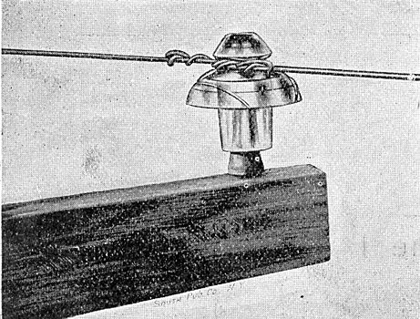
The power line consists of three No. 3 bare copper wires arranged in a triangle, one wire being at the top of the pole. The wires are carried on glass insulators that are especially designed for the voltage at which the plant is operated. The insulator pins and cross-arms have been specially treated to preserve their insulating qualities and protect them from the weather. The two wires of a telephone circuit are carried upon bracket pins below the power wires, and by careful attention to transposition the telephone service has been made perfectly satisfactory and safe. The poles are white cedar, the standard length being 30 ft., although some are of necessity considerably longer. The triangle formed by the power wires is not quite an equilateral one, and for this reason the power wires are transposed twice in the length of the line. All angle poles have double cross-arms and fixtures and are substantially braced. All spans longer than the standard length (125 ft.) have double poles on each side of them, each pole having double cross-arms and fixtures.
In addition to the lightning protection at each end of the line, in the power station and receiving station, there are Wurts lightning arresters installed at four intermediate points on the line.
At present there is one receiving station at Cripple Creek; another is in course of erection. Here the current is transformed from 20,000 to 500 volts, and distribution is made at the latter voltage. The arrangement of the apparatus in the substation is in general similar to that in the transformer house at the power station, about the only difference being that here the circuit breakers for automatically cutting out a disabled transformer are in the low-voltage circuit, and the transformer fuses in the high-voltage circuit.
| |||
| Fig. 11. - Mining Hoist. |
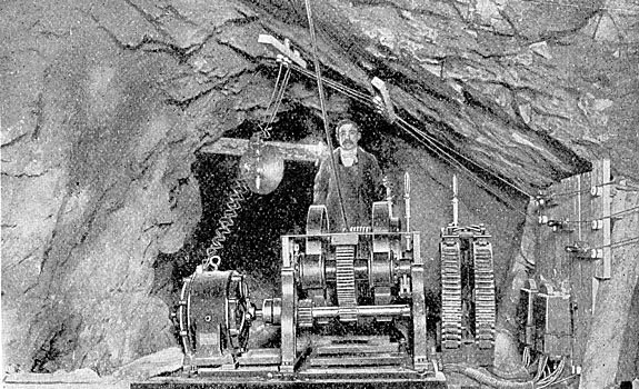
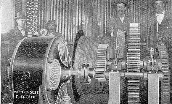
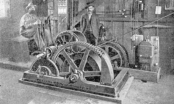
So far only hoists are being operated, though a number of motors are being installed for driving mills, pumps and compressors. Some of the hoists are illustrated in Figs. 11 to 14. They are driven by means of Westinghouse three-phase induction motors, whose speed is controlled by means of auto-converters in connection with a commutator type controller. The method of handling these hoists is as simple as that of the steam hoists which they replace, and the men who run the latter find no trouble in operating the electric hoist. The starting of the electric hoist is more gradual and the running smoother than the steam hoist. There is no boiler to fire and keep in repair and no coal and water to look after. Of the hoists illustrated in this article, those in Figs. 12 and 14 were supplied by the Stearns-Roger Mfg. Co., of Denver, and that in Fig. 11 by the Hendrie, Bolthoff Mfg. Co., Denver, all being operated by Westinghouse induction motors.
| |||
| Fig. 12. - Motor and Gears of One of the Hoists. |
The cost of power in the Cripple Creek district when generated by steam is high, riot only because of the price which must be paid for coal, but because in most cases water for the boilers must be hauled by wagon from some distance and up steep grades. In some cases the cost of water for the boilers equals that of the fuel.
| |||
| Fig. 14. - Type of Mining Hoist. |
Power is being supplied by the Colorado Electric Power Company at a price considerably less than the cost when steam is used, especially in the case of small plants. This, in connection with the advantage of greater flexibility and ease of operation, creates a steady demand for electric power which is being filled as rapidly as motors can be obtained. It bids fair to be but a short time until the present plant is loaded to its full capacity.
