[Trade Journal]
Publication: American Electrician
New York, NY, United States
vol. 14, no. 12, p. 596; 47, col. 2-3
NEW
Apparatus
AND
Appliances.
·
·
NEW PORCELAIN ELECTRIC SPECIALTIES.
The accompanying illustrations show various porcelain electric specialties recently brought out by Pass & Seymour, of Sobray [sic] Solvay, N. Y. Fig. 22 shows a porcelain junction box or transformer cut-out, which is especially adapted for use in electric light stations and isolated plants. It is finished in two styles, one style having a white glazed finish, while the other style is provided with a black enamel finish. This latter finish is not merely thrown on, but the cut-outs are dipped and are then baked; resulting in a finish which will stand the weather and which is at the same time pleasing in appearance. Its chamber is entirely surrounded by porcelain, and is completely divided by means of projections on the plug. The plug is held in the back by means of knife contacts capable of holding a wire from the smallest size up to No. 4, and also capable of taking a 5-in. fuse. The cut-out is fastened into place by means of lag screws furnished by the makers.
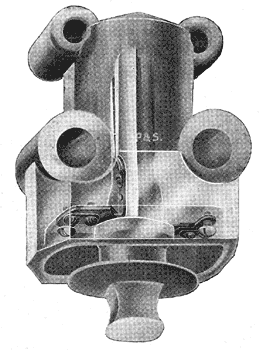 |
| Fig. 22. - Junction Box. |
The angle receptacle shown by Fig. 23 was especially designed for show window work and possesses many features of advantage not found in the ordinary receptacle. By its use, a downward distribution of light is obtained. It is made both with and without a key, and can be used with either concealed or open wiring. It is designed as the illustration shows for a shade holder.
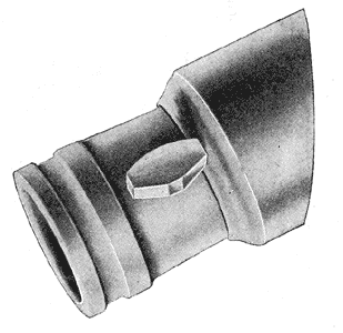 |
| Fig. 23. - Angle Receptacle. |
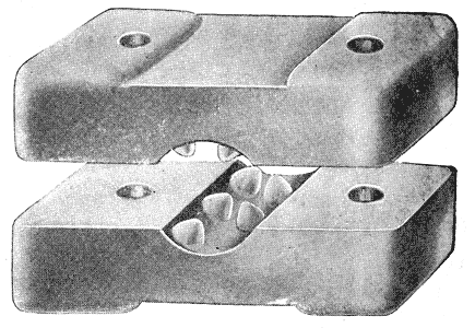 |
| Fig. 24. - Single-Wire Cleat. |
The single wire cleat shown by Fig. 24 is strong and durable. It is made in two sizes and both glazed and unglazed. It will take wire in sizes from No. 14 to No. 2, and is so designed that when put in place the wires cannot slip and the insulation of the same is preserved.
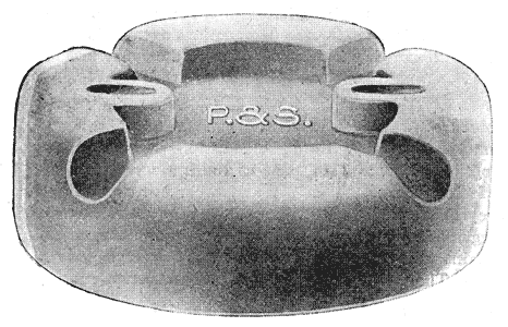 |
| Fig. 25. - Switch Base. |
The switch base shown by Fig. 25 was designed to take the place of the small knobs which have been used heretofore quite frequently in putting up surface switches on open cleat work. The base may be used with any five or ten ampere switch with either a single or double pole. The strain insulator shown by Fig. 26 is made in two sizes, one to take a wire as large as in. in diameter, and the other to take a wire as large as in. in diameter. Strength is the principal characteristic of the insulator and it is warranted to withstand the breaking strain of any of the wires mentioned.
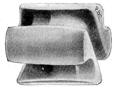 |
| Fig. 26. - Strain Insulator. |
