[Trade Journal]
Publication: The Electrical Engineer
New York, NY, United States
p. 511, col. 1-2
THE LOCKE INDESTRUCTIBLE STEEL INSULATING PIN AND INSULATORS.
In these days of ever increasing potentials in power transmission work high line insulation is a sine qua non. But the older applications such as the telegraph and telephone have so long been suffering from the baneful effects of bad insulation that the tendency towards better line insulation is making itself felt to a marked degree, as evidenced by the use of improved line material of all kinds. Concentrating his efforts on this branch of work Mr. Frederick M. Locke, of Victor, N. Y., has brought out a variety of line material some of which we illustrate in the accompanying engravings.
Next to the insulator itself, the pin on which it is mounted claims attention from the line constructor. For this purpose Mr. Locke has designed a steel insulating pin. This pin is constructed with a steel bolt passing from the top of the pin through a half inch hole in the cross arm, and is securely fastened on the underside by a nut and washer. The iron cap between the top of the insulator pin and the cross arm serves as a brace to resist the strain of the pull on the pin, and at the same time covers the pin hole in the cross arm, thereby keeping out water and moisture and preserving the arm.
The pin evidently is unbreakable and does not rot like a wooden pin. Another great advantage lies in the fact that it does not weaken the cross-arm nearly so much as the ordinary wooden pin, the difference in the diameter of the pin hole being that between 1/2 inch and 1-1/4 inch.
| |||
| Fig. 1. Locke Indestructible Steel Insulating Pin and Insulators. |
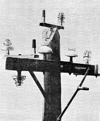
As shown in the engraving, Fig. 1, they can be used bottom side up on the underside of a cross arm when it is desired to add wires to a line without increasing the number of cross arms. For iron pole fittings a 3/8 ich by 5 inch pin is made, which can readily be attached, and when in place is neither cumbersome, expensive nor inconvenient as is the case when ordinary black-smith fixtures are used.
In Fig. 1 there are shown a few of the many uses to which the indestructible steel insulator pin may be put. As will be observed the pins can be attached to the top, bottom and sides of the cross arm, or to pole tops, break arms, or to cross arm braces. Wherever placed, they present a neat appearance and may be depended upon to resist all reasonable strains of line construction. The illustration also shows the Locke patent break arm in position under and on top of the cross arm, also the Locke large triple petticoat porcelain insulator, triple petticoat glass insulator, transposition insulator and cable insulator.
| |||
| Fig. 2. Locke Insulator. |
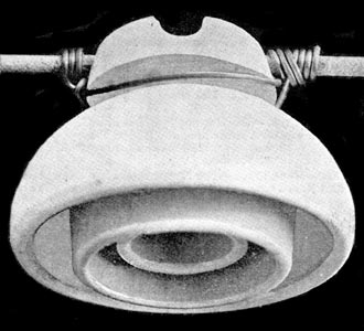
The triple petticoat china insulator, shown in Fig. 2, is made from the highest grade chinaware. It measures 5-1/4 inches in diameter and 4 inches in height, and has over 12 inches of surface between the wire contact and the supporting pin. About 10 inches of this surface is on the under side of the insulator, out of reach of direct rainfall, where it keeps comparatively dry. The surfaces of the bottom of the insulator are perpendicular, and therefore catch no foreigh matter. By repeated practical tests it has been found that a potential of 85,000 volts is required to puncture the insulator; hence it will carry with safety and economy any voltage that is practicable for use in the commercial application of electric power.
The body and glaze of these insulators are of simple earths only, fused together into a vitreous, homogeneous mass at the greatest heat. No lead or other metallic oxide being used in making, the glaze is not a conductor. The body and glaze being of exactly the same material and fired at the same heat, the insulating qualities are as high without as with the glaze.
