[Trade Journal]
Publication: Electrical World and Engineer
New York, NY, United States
vol. 40, no. 6, p. 205-208, col. 1-2
Missouri River Power Company's 50,000-Volt Transmission Plant.
BY A. W. CLAPP.
AS noted in the ELECTRICAL WORLD AND ENGINEER of March 15, the Canon Ferry, Montana, generating station of the Missouri River Power Company early in the year began the supply of current at 50,000 volts for transmission to Butte, 70 miles distant. Since that time the plant has been supplying current continuously to Butte, being thus the first plant in the world to operate normally at such a voltage. The Canon Ferry plant, which was completed in 1899, was described in the issue of July 13, 1901, of this journal, and some of its constructional features were the subject of an article in the issue of June 7, 1902. Since the earlier articles a number of improvements have been added, of which it is the object of this article to give some account, as well as of the new Butte substation.
| |||
| Fig. 1. General View of Canon Ferry Power Plant. |
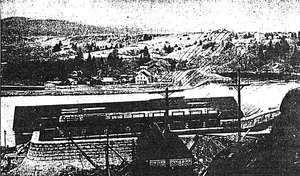
As stated in the previous description, the power house at Canon Ferry is a rock-faced granite building 225 x 50 feet inside and 28 feet in the clear below the roof trusses, with a steel and concrete arch gallery along the west side 17 feet 6 inches, wide and 13 feet 6 inches clear below the roof trusses. This gallery also extends across the north end of the power house, affording ample room for offices, etc. All of the space between the edge of this gallery and the east or river side of the house is covered by a 15-ton crane, furnished, as was all the steel work, by the American Bridge Company.
Penstocks beneath the gallery enclose the pairs of turbines, which are direct-connected to the generators, both being carried on I-beams across tail races 15 feet wide by 12 feet deep, formed by granite walls 5 feet thick, spaced on 20 feet centers. On the west side of the main power house a steel and corrugated iron addition 156 feet long, occupying the space between the power house and the canal wall, and having its floor just above the penstocks and on a level with the gallery floor, affords room for the six 950-kw transformers mentioned later.
The original installation consisted of four two-phase, 750-kw, 550-volt generators, direct-connected to pairs of Dayton Globe Iron Works turbines, three of these being controlled by Replogle governors, and the fourth by a Lombard governor. There were two 90-kw, 125-volt exciters direct-connected to separate turbines. From a white marble switchboard with four sets of busses the current was carried from four transformer panels over sixteen 1,000,000-cm., lead-covered cables to a separate transformer house, where there were eight 325-kw transformers, oil-insulated and self-cooled, in four sets connected to transform from 550- volts, two-phase, to 11,000 volts, three-phase. At this pressure the current passed through a plug-board Westinghouse lightning arrester, and into four feed lines of No. 4 solid copper which led to another plug board of similar construction at East Helena, and from there to the company's various services in and around that city.
The changes and additions recently made include the moving of these transformers and plug boards on the main gallery of the power house and the arresters into the addition; the purchase of four more transformers of the same capacity, and the changing over from the old switchboard to an entirely new one. The four generators were also changed from two-phase to three-phase by the addition of brass fish-plates to stiffen the laminations at each end of the armature, and the substitution of new ventilated type, three-phase collector rings for the original two-phase rings. The new apparatus installed consisted of six three-phase, 750-kw, 550-volt Westinghouse generators, direct-connected to pairs of 45-in. turbines, furnished by S. Morgan Smith Company, York, Pa.; one 225-kw, 150-165-volt exciter connected to another turbine; seven Lombard governors and another exciter of 150-kw capacity driven by a 150-hp, 550-volt induction motor. There were also installed six 950-kw, 550-50,000-volt transformers, together with 12 static interrupters, six lightning arresters, fused circuit-breakers, etc., at Canon Ferry, and a duplicate equipment in the Butte sub-station. These 12 transformers can all be connected with 550-volt or 2,200-volt to 25,000-volt or 50,000-volt, and are supplied with extra strips for adjustment to meet running conditions.
| |||
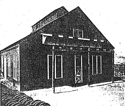
| Fig. 2. Transformer House. |
| |||
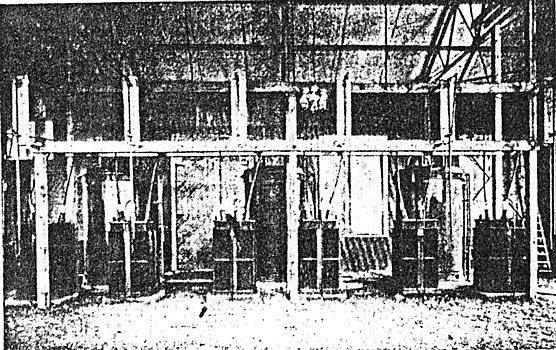
| Fig. 3. Transformers. |
The main switchboard at Canon Ferry is 47 feet 4 inches by 9 feet 9 7-16 inches high, of blue Vermont marble, finished in polished copper and black enamel, and is located centrally on the gallery. At the left of the board arc six 325-kw, 550-11,000-volt transformers, in two groups. At the right is an exciter board of four panels with two pairs of busses adjacent to six more transformers like those on the left; and lastly, a four-panel plug-board to control the 11,000-volt output of these 12 transformers and distribute it as desired to the four feeder lines before mentioned. Front either end of the main switchboard the arrangement is as follows:
1. Five generator panels, each carrying one, field ammeter, one alternating-current ammeter and one long scale polyphase watt?meter, two circuit-breakers, nine 1,200-ampere U-blade switches, synchronizing lamp of 5 cp and synchronizing plug.
2. Two feed panels, each controlling three of the 325-kw transformers and equipped with three ammeters connected to three 5-ampere series converters directly in the circuit of each transformer, three circuit-breakers and nine 2,000-ampere U-blade switches.
3. One feed panel similar to the last two, but equipped for 3,000 amperes per leg, and controlling three of the 950-kw, 550-50,000-volt transformers. The eighth panel from either end is, a junction panel equipped with 4.000-ampere. U-blade switches, for joining the halves of the sets of busses, and on its upper section carrying six polyphase indicating wattmeters, one connected to each feeder circuit.
The nine separate bus-bars are built of 1/8-in. x 3-in.-rolled copper; there are a number of strips on each bus, increasing gradually front six at the outer end, of the board to 30 strips opposite the fifth generator panels. Small marble panels in front of the main board, on the I-beam carrying the crane rail, furnish a mounting for field switches and voltmeter plugs, and six polyphase integrating wattmeters connected to the feeder circuit. Directly below the field switches are the corresponding rheostat pedestals connecting to base-plates, and hung below the gallery floor. The rheostat, which is of the cast-grid type, is also mounted below the gallery floor.
There are four voltmeters swinging at each end of the board, three for each hall set of the three bus-bars, and one throwing-in voltmeter for the five generators on each half. The alternating-current indicating instruments are all long scale, and of exceedingly wide range. All switches are of the latest unit-blade type of very ample capacity, while the current density in busses and cables is nowhere allowed to exceed 500 amperes per square inch. All circuit-breakers are non-automatic, of the air break brush type, of ample capacity, and easy operation.
During the period of change from the old two-phase to the new three-phase switchboard, the two systems were run in parallel on the 11,000-volt side for several days with perfect satisfaction.
From each of the four small feed panels six 1,000,000-cm., lead-covered cables are led through an open cableway level with the top of the switchboard directly to the 325-kw transformers, the circuit-breakers on the board being connected each in one leg at the transformers, as are also the ammeters.
From the high-tension side of the transformers, No. 4 9/32 rubber-covered units lead straight to a cross-arm on the roof trusses, thence distributing to the proper wire of 12 busses, which are supported on the roof trusses, and leading down to the 11,000-plug-board at the extreme right. During the various changes necessitated during construction these busses were found very convenient for facilitating the removal of transformers, changing from two-phase to three-phase, etc. From the plug-board current passes through lightning arresters in the addition to the power house, and thence straight tip through the nearly flat roof of the addition. The insulation consists here simply of rubber-covered wire drawn through 2-in. x 36-in. glass tubes which are supported by split wooden bushings; the tubes are surmounted by 12-in. conical galvanized taps tapped to a watertight joint next to the wire. The wooden bushings are flashed to the roof to form a water-tight joint, and are lag-bolted to the roof.
The 550-volt leads are brought out through the roof in an entirely similar manner through glass tubes 2 inches x 40 inches, with light cone of heavy waterproof canvas and dry wooden frame, with a base diameter of 18 inches, used for a protection from moisture.
From each of the two large feed panels eighteen 1,000,000-cm. cables lead through convenient doorways, pass along the wall of the addition, and thence span a distance of about 5 feet to the low-tension terminals of the 950-kw transformer sets. One leg of each transformer can be opened by the circuit-breakers on the main board, the other leg by knife switches, located in the doorways mentioned above.
The high-tension leads of the transformers pass first through static interrupters, then through fused circuit-breakers on one leg and a plain knife switch on the other leg, thence connecting to three bus wires of heavy rubber-covered wire overhead. The outer end of each of these busses connects through fused circuit-breakers through the roof to one of the two three-wire lines to Butte. The inner ends may be tied together by similar fused breakers. Thus either transformer set may feed either line, or both may be fed in parallel or separately. Also, any transformer may be entirely cut out by opening both high-tension and low-tension leads, without interrupting the service.
The static interrupters are comparatively novel. Their theory and commercial form were fully described by Mr. Thomas in a recent paper before the American Institute of Electrical Engineers. They consist essentially of a choke coil in series with the transformer lead, and a condenser connected on the transformer side of the choke coil to ground, the whole immersed in oil. The ground current from this condenser has been put to a novel use by the electrician of this company. The Weston alternating-current voltmeter is used as an ammeter connected in the ground circuit of the condenser to determine the condition of the transformers and attached line relative to ground; the induction being fully that of the dynamic current, many bothersome features of the ordinary static inductor are avoided. There are, of course, sources of error, but these do not prove troublesome.
The main transformers are water-cooled, but the coils being about 6 feet above the level of the water in the forebay, it was necessary to have recourse either to pump circulation or to some form of siphon. Main intake pipes in duplicate, supplied with proper strainers, were brought in through the canal wall below low water level. The transformer coils were bridged between there and other pipes leading 30 feet down to the tail races. These intake and discharge pipes were connected by a valve which allows water to flow directly through the discharge pipe vents, thus starting a. vacuum, This valve is then closed, and water is immediately siphoned through the transformers. A common vacuum gauge shows the condition as to vacuum, while in the discharge pipe of each transformer a small brass pipe 12 inches long and 3/8 inch small and 1 1/2 inches large diameter has a single mercury U-tube connected between the central small diameter and the upper end of the pipe, affording an accurate indication of the amount of water circulating through the transformer.
 |
| Fig. 4. Three-Petticoated Insulator. |
Each of the six cables of the two feeder lines to Butte are protected by lightning arresters at Canon Ferry and Butte. These cables are of seven strands of copper aggregating 106,500 cm. each, mounted on special glass insulators designed by H. M. Gerry, Jr., chief engineer and manager of the company, and made by the Hemingray Glass Company, Covington, Ky. The insulator proper is three-petticoated glass 5 1/8 inches high and 9 inches diameter, the pin extending as near as possible to the wire groove below the insulator; extending up inside the inner petticoat is a tapered glass sleeve 5 1/2 inches diameter at its lower end, clearing the cross-arm by 1 1/4 inches, and supported on a 1 1/4 inch shoulder on the pin. The pins are all seasoned oak, still further dried and impregnated by boiling in hot paraffin, so that the pins themselves stand 100,000 volts on test. The pins are 12 inches long above the butts, 1 1/2 inches at top of thread, which is of standard pitch. The maximum diameter is 2 1/2 inches, tapering on a 60-degree angle at the top of this butt, whose diameter is 2 inches for the pin which fits the cross-arm, and 2 1/8 inches for the pin which fits the pole tops. These latter butts are 8 inches long, the former 5 1/2 inches, and a special reamer insures a close fit of the 60-degree taper at the top of the pole and on the cross-arm. The distance between the line cables is 18 inches. The pole lines are 40 feet apart, and the right of way is entirely cleared of trees, etc. The poles are of Idaho cedar, 8-in. tops, and in length from 35 to 90 feet, all poles above 75 feet being spliced.
The Butte sub-station is a steel and corrugated iron building, 60 ft. x 80 ft. x 20 ft. studs, the feeder lines entering at one end through glass tubes 2 in. x 48 in. passing through a wooden panel and protected from the weather by a shed roof overhanging about 5 feet.
Low equivalent arresters, fused line breakers, paralleling breakers and breakers on each leg of the six 950-kw transformers, together with the static interrupters, are practically a duplicate of the equipment at Canon Ferry. The arresters, line and tie breakers are at the end of the building; the transformers are along each side of the central court, toward which all breakers open. The main switchboard here consists of two 40 in. x 9 ft. 9 in. panels with three circuit-breakers three ammeters and six knife switches, each connecting the low-tension (2,200 volts) of the transformers to either or both of the two bus sets. As at the generating station, the switchboard circuit-breakers open one leg of each transformer circuit, while a knife switch mounted on each transformer case opens the other leg. These transformer cases are very substantially built of heavy boiler steel, with cast-iron and walnut covers bolted on and hold about 16 barrels of transformer oil each. A pair of synchronizing lamps and a swinging voltmeter are provided. Integral with these two panels on either side are panels 20 inches wide, on which are mounted the sets of feeder instruments, three ammeters and one polyphase indicating wattmeter. These feeder circuits feed out through three-pole, double-throw General Electric oil switches to bare stranded cables of 600,000-cm. section, leading to the company's various loads in Butte.
| |||
| Fig. 5. View of Interior of Power House. |
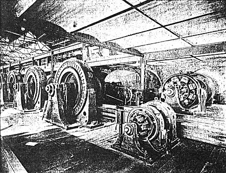
There are at the present time three of these feeders, and the switchboard instruments are provided with an unusually ample range so as to read starting motor currents and even short-circuited currents. All feeder wattmeters take their series currents from three to five-ampere, series-connected coils directly in each transformer circuit, the three currents being combined into two circuits of 8.6 amperes each at full normal speed, through the two coils of the wattmeter. The shunt circuits are fed from auto-converters at Canon Ferry, and shunt transformers at Butte. These meters have a long and uniform scale, and are intended to be very accurate under all conditions. The wattmeters at the Canon Ferry generating plant are also of the polyphase type, but are connected according to the more common scheme of two wattmeters on three-phase circuits.
As before stated, all station electrical apparatus is of the Westinghouse make, except a few oil circuit-breaking switches at Butte. Nearly all consuming apparatus at Butte, however, is General Electric. This apparatus, aside from incandescent lighting to the mines, consists entirely of induction motors ranging from one to 800-hp capacity, there being at the present time only one of the latter size driving an air compressor at the Anaconda mine at constant full load. Most of the motors from 50 to 300-hp capacity are equipped with rope drive. Some of the smaller motors are direct-connected to 500-volt generators, furnishing direct current for cranes, mine trolleys, etc. Power is supplied for a great variety of purposes at the great copper mines and to the smelters and various reduction works at Butte.
