[Trade Journal]
Publication: Electrical World
New York, NY, United States
vol. 50, no. 10, p. 443-446, col. 1-2
The 50,000-Volt Line of the
Taylor's Falls-Minneapolis
Power Transmission.
IN the first issue of the ELECTRICAL WORLD for July was an article descriptive of the power plant at Taylor's Falls, on the St. Croix River, which was recently erected to supply the Minneapolis General Electric Company with power. The present article takes up the 50,000-volt transmission line which connects this power plant with Minneapolis. This line is 40.6 miles long and is designed to carry the total present capacity of the Taylor's Falls plant-namely, 10,000 kilowatts-with a line loss of 6 per cent and a voltage drop of to per cent. It is built in almost an air line from the west side of the St. Croix River and Taylor's Falls to a sub-station at the city limits of Minneapolis. At the Minneapolis sub-station are step-down transformers for reducing from 47,500 to 13,800 volts. From this sub-station the transmission is at 13,800 volts to the various stations and sub-stations of the Minneapolis General Electric Company. The Minneapolis distributing system and the work of preparing to receive and distribute Taylor's Falls power in Minneapolis will be the subject of a later article.
POLE LINE.
A right of way 60 ft. wide was purchased for the entire line. The right of way, however, is not fenced in, and farmers are allowed the use of the land just as before the purchase. The general direction of the line is northeast and southwest, so that it cuts diagonally across all fields. As the highways follow the section and half-section lines, the nearest highway zigzags across the line from one end to the other. As the country is dotted with small lakes, a number of these had to be crossed, and for such crossings steel towers were employed.
| |||
| Fig. 1. - Straight Line Construction and Telephone Booth. |
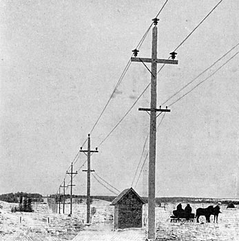
Fig. I is from a photograph of the typical straight-line construction. This shows also one of the telephone booths. Fig. 5 is a drawing showing the dimensions on a standard straight-line pole. The separation between wires is 6 ft. The conductors are No. 4-0 stranded, semi-hard-drawn copper. A four-pin telephone cross-arm is placed 7 ft. below the transmission line. The poles are set from 100 ft. to 120 ft. apart and vary in length according to the local conditions and contour of the country from 40 ft. to 60 ft., the object of this being, of course, to avoid too sudden changes in the level of the conductors. The following pole dimensions were specified:
For a length of 40 ft .... Tops 8 ins., butts 15 ins.
For a length of 50 ft .... Tops 9 ins., butts 16 ins.
For a length of 60 ft .... Tops 10 ins., butts 18 ins.
The cross-arm braces are of 1-1/2 in. x 3/16 in. angle iron 3 ft. 7-5/8 ins. long. The main transmission cross-arms are 7 ft. 4 ins. long and 5 ins. x 7 ins. in section. There are in all 12 telephone booths in 40.6 miles of line. There is a patrolman's cottage at the half way point, the other patrolmen living at Taylor's Falls and Minneapolis. For crossing lakes four sizes of steel towers are used-40 ft., 45 ft., 50 ft. and 60 ft, in height. These were made by the Aermotor Company, of Chicago, and are shown in some of the accompanying illustrations. Conductors are spaced 7 ft. apart op towers. There are 27 steel towers on the line on account of the large number of bogs and lakes to be crossed. The telephone wire is No. 10 semi-hard-drawn copper. Double cross-arms are used at all curves and pronounced changes in the profile.
| |||
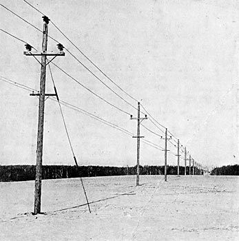
| Fig. 2. - Line Construction at Guyed Pole. |
| |||
| Fig. 3. - Line Crossing Railroad Cut. |
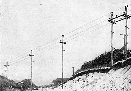
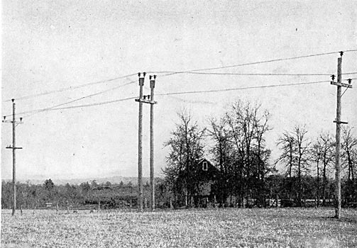
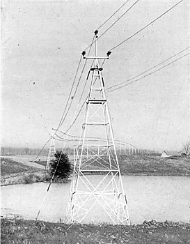
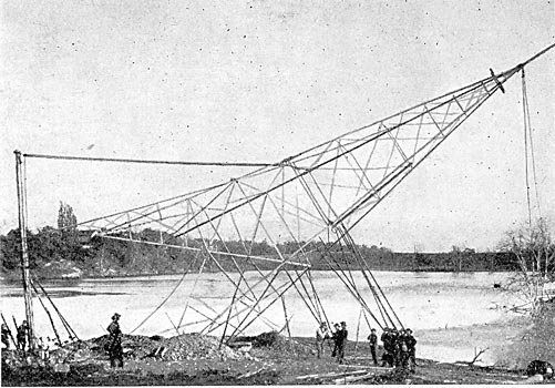
Fig. 2 is from a photograph of the line construction at a guyed pole at which the cross-arms and pins are double. Fig. 6 is a drawing of the construction of such a pole, showing the make-up of the guy in detail. Fig. 3 shows the double pole construction used at a railroad crossing at a cut. Fig. 8 is a drawing of the same construction giving dimensions and foundation details for use when crossing a narrow stream. Fig. 4 shows the arrangement at the transposition of the transmission conductors. A transposition of one-third turn occurs every 3-1/2 miles. A double pole is used for this purpose. The telephone line is transposed every tenth pole. Fig. 9 shows a pair of steel towers at the crossing of Leedholm Lake. The process of raising a 60-ft. steel tower is shown in Fig. 10.
| |||
| Fig. 4. - Transmission Pole. |
 |
| Figs. 5, 6, 7 and 8. - Various Types of Poles. |
| |||
| Fig. 9. - Steel Towers on Leedholm Lake. |
| |||
| Fig. 10. - Raising A 60-Ft. Tower. |
INSULATORS AND PINS.
The transmission line insulator used is known as S. & W. No. 1, made by Locke. A cross-section of this insulator is shown in Fig. 11. It consists of four parts held together with neat cement. These insulators are shipped in crates assembled, but without pins. The crates were provided with holes just the right size to take in the pin. The cementing in of pins was done before the insulators were uncrated, the crate thus serving the purpose of a template to hold the pins in position while the cement dried. The insulator, as seen by the drawing, is 12-1/4 ins. high by 14 ins. in diameter over all. The four parts were tested before assembling with a 60-cycle, 200 kilovolt-ampere testing set. The top-piece withstood a test pressure of 60,000 volts; the second shell, 40,000 volts; the third shell, 50,000 volts, and the fourth inner shell or center, 50,000 volts. The assembled insulator without cement was tested at 120,000 volts.
 |
| Fig. 11. - Cross-Sectional Elevation of Insulator. |
The strain insulators, as shown in the guy-wire in the illustrations, consist of pieces of oak 2-1/2 ins. x 2-1/2 ins. and 30 ins. long, boiled in linseed oil. A tie-wire of No. 2 solid copper is used for fastening the No. 4-0 stranded conductor on the 50,000-volt insulators.
The insulator for the telephone line is a double petticoat 2300-volt porcelain insulator placed on a locust pin with a white-pine cross-arm. The cross-arms of the transmission line are of fir, unpainted.
 |
| Fig. 12. - Cross-Arm Insulator Pin. Fig. 13. - Insulator and Pin. |
The pins for the transmission insulators are made from 2-in. extra heavy steel pipe, with ends wedged down for cementing into the insulators. Fig. 12 shows the pin used on the cross-arms. This pin is held by a bolt passing at right angles through the cross-arm. The pins used on the pole tops have their lower ends flattened so as to bolt against the pole. Fig. 13 shows the pole-top pin. Two pins out of every 100 are tested and must stand a lateral strain of 2000 lbs. applied at a point 1 in. above the top without yielding.
LIGHTNING PROTECTION.
Few transmission lines have had so much attention given them as regards lightning protection. Minnesota thunderstorms are very severe, and it was felt that with a line of so much importance, upon which the electric light and power service of a great city might be dependent, there was every reason for obtaining the best in lightning protection. Of the lightning protection appliances about to be described, many are of a partially experimental nature and have been put up with a view to determining points about which there is at present considerable uncertainty. Owing to freshets which caused unexpected delays in the completion of the power house, the transmission line was finished some time in advance of the other work, and this gave opportunities for some experiments with lightning protection apparatus during the summer of 1906. Mr. N. J. Neall, of Boston, the specialist in lightning protection, has been acting as consulting engineer of this part of the work.
At each end of the line and in the middle horn-type lightning arresters have been installed in accordance with Fig. 15. A rectangular cross-arm frame is built between four poles and the necessary insulators mounted on these cross-arms.
 |
| Fig. 14. - Choke Coils. |
 |
| Fig. 15. - Horn Type Lightning Arrester. |
The horn spark-gap is adjustable from 0 in. to 12 ins. Underneath the arrester is a platform, also mounted on transmission insulators.
A water-column resistance can be inserted in the series with a ground wire from this arrester, this water column resistance being described later. The choke coil used in connection with lightning arresters is shown in Fig. 14. There is also a platform under these choke coils, so that the paper in the tell-tale spark-gaps, which are placed in shunt around choke coils, can be renewed. A tell-tale spark-gap which has been used in large numbers in getting records of static discharges on this line is shown in Fig. 18. Fig. 17 shows the framing used in connection with the adjustable spark-gaps, telltale spark-gaps and fuses installed for obtaining records on discharges.
The water-column resistance before referred to, which can be used in series with the ground wire of the horn arrester, is shown in Fig. 16. It consists of three galvanized iron tanks or funnels, one for each leg of the circuit. These are mounted on transmission insulators and each is connected to the ground wire from a horn arrester. In the bottom of these tanks are four nozzles, one or all of which can be turned on according to the amount of water-column resistance it is desired to insert.
 |
| Fig. 16. - Water-Column Resistance. |
Water from these nozzles falls into a grounded iron pan. This iron pan can be adjusted in height, as shown by the drawings, being suspended on pulley blocks. The water supply is piped to the arrester tanks by pipes discharging several feet above the tank. For purposes of obtaining records, every pin on every third pole of the transmission line has been grounded through a tell-tale spark-gap. Several experimental schemes of overhead grounds have also been installed on different portions of the line to determine the best construction. One form of overhead ground is to place a grounded wire at the center of the transmission wire triangle. Another plan has been to place grounded wires directly above the two lower wires of the triangle. Still another plan has been to place a lightning rod on each pole with its point above the top wire of the transmission triangle. This lightning rod is fastened to the pole, and is bent out around the top transmission wire to keep it a safe distance away. Another lightning rod scheme installed is that of placing lightning rods on separate poles set alongside the transmission line, the rods extending about 25 ft. above the level of the top transmission wire. Tell-tale spark-gap boxes are inserted in all ground wires. The line is looked after by four patrolmen.
 |
| Fig. 17. - Spark-Gap Framing. |
 |
| Fig. 18. - Tell-Tale Gap. |
Stone & Webster, of Boston, are general managers of the property and did the engineering and constructing, both on the power plant and the transmission system.
