[Trade Journal]
Publication: Electrical World
New York, NY, United States
vol. 50, no. 11, p. 528-529, col. 1-2
A Year's Operation of the Highest Working
Voltage in the World.
BY F. E. GREENMAN.
The Grand Rapids-Muskegon Power Company has been operating its transmission line at 72,000 volts for the past year, with results far beyond expectation.
This transmission line extends from Roger's Dam, located six miles south of Big Rapids in a southerly direction, to the Casnovia switch house, 40 miles from the dam, where the line branches to Grand Rapids, 26 miles south and Muskegon, 26 miles west, making a total of 92 miles, located entirely upon private right of way, four rods wide, cleared of all trees and underbrush and a, large portion fenced. Considerable care was used in obtaining the right of way to get the longest possible tangents and moderate grades. Almost the entire distance from Roger's Dam to Croton, the line runs through the pine stump land which only a few years ago helped make Michigan famous; but now is a dreary waste of blackened stumps and brambles. In order to have the line properly patrolled, it was necessary to construct a well-made road bed over a greater portion of the right of way; care being used to have it properly drained so that it could be depended upon in all kinds of weather.
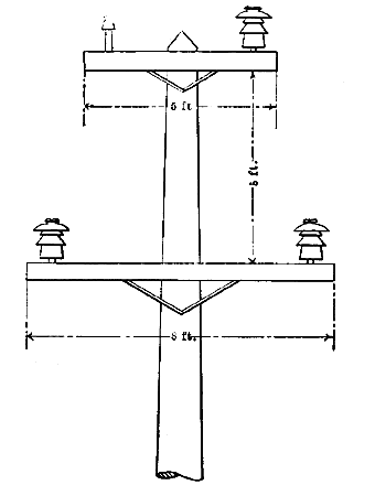
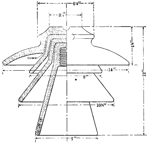
In construction, wooden poles were used exclusively, carefully selected, varying in length from 35 to 75 ft-with diameter of tops from 8 ins. to 12 ins. The special 8-ft. and 5-ft. cross-arms were employed, spaced 5-ft. apart, as in Fig. 1, and carrying three 14-in., 4-part insulators, as shown in Fig. 2, mounted on 18-in. wooden pins except on corners and angles, where a galvanized steel tubular pin with cast lead thread forms the pole construction.
No. 2 medium hard-drawn bare copper was used for line conductors together with No. 10 galvanized iron wire grounded every fifth pole for lightning protection.
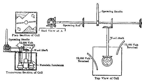
The 72,000-volt switches used at the dams, switch house and sub-station, were designed and constructed under the direction of Mr. J. B. Foote. The construction is shown in Fig. 3. They are mounted in a wooden case, made as nearly oil-tight as possible, and the case is enclosed in a galvanized iron tank. The finger contacts are mounted on 40,000 volt insulators, placed in opposite corners of the case. A heavy wooden block is so placed in the other corners of the case as to allow the switchblade a throw of 90 deg. This blade is mounted in the center on a wooden shaft, insulated with porcelain bushings; the shaft extends through the top of the case, where one of the four bevelled [sic] beveled gears which operates the device is attached, as shown in the sketch. These switches have given perfect satisfaction, combining two very desirable features-maximum efficiency and minimum cost. Three sets of these switches are located at the Casnovia switch house, so that either the Grand Rapids or Muskegon, or both branches, may be cut out at the will of the operator in case of trouble or for testing purposes.
 |
| Fig. 1 — Arrangement of Cross-Arms. |
The patrolling of the line has been done by two men, one located at Roger's Dam, patrolling to the Casnovia switch house, and the second located at the Casnovia switch house, patrolling the Grand Rapids and Muskegon branch alternately. This arrangement has been found quite satisfactory, the entire line being covered four times each week. Each man is equipped with a good, strong, specially made buggy, of sufficient size to carry three or four high-tension insulators together with pins, portable telephone, etc. In order to keep in touch with patrolmen when on the line, they call the Grand Rapids sub-station every half hour over the private telephone line. Thus in case they are needed on short notice they can be easily communicated with.
 |
| Fig. 2 — Part Sectional Elevation of Insulator. |
The usual amount of trouble caused by insulators being broken by stones and guns was experienced during the first few months, but after several of the culprits were caught and punished in the courts, very little trouble was had, and in the above cases very little damage was done beyond the replacing of an insulator. We find, as with all high-tension transmission lines, lightning is the greatest enemy; but by comparison no greater difficulty has been experienced than with lines operating at 20,000 volts, presumably because of the higher insulation used at 72,000 volts.
During the year there were two total interruptions caused by lightning demolishing insulators. On two occasions wires were thrown across the line, and one interruption was caused by a broken pin, allowing a wire to rest on the cross-arm, which it burned off. In connection with the last named interruption, the static discharge from the line is gradually charring the wooden pins. While this is not sufficient to cause alarm, Mr. Foote is making preparation to replace them with galvanized steel tubular pins, such as now used on corners, as soon as convenient.
No difficulty has been found with leaking insulators not broken or cracked, as seems to have been experienced on other lines, although in some localities they have been put to a very severe test, such as A portion of the line passing plaster or gypsum mills where everything is covered with the white gypsum dust. The Writer has noticed on several different occasions that the insulators were practically covered, petticoats and tops, and at this particular place there are two sharp turns and a railroad crossing where all poles are double armed. Still there has been very little discharge, if any-at least no more than could be found on close inspection of a clean, dry insulator. Such discharge is, of course, more noticeable during weather that is cold and dry than when it is warm and damp, for the reason that the static or leakage is absorbed and diffused in a humid atmosphere, whereas in dry, cold weather, it must be condensed until of sufficient voltage to jump the gaps necessary to reach the pin.
DISCUSSION.
Following the reading of Mr. Greenman's paper many questions were asked of the author which brought out the following points:
A telephone circuit is operated satisfactorily on the main pole line. This telephone line is the best tell-tale of trouble the company has and gives the first warning of leaky insulators. The line has been operated for 14 months at 72,000 volts. Loss from power-house bus-bars to customers' 440-volt meters is 23.5 per cent average. The losses included in the 23.5 per cent are those in the step-up transformers, high-tension line, step-down transformers at city limits and a second set of step-down transformers at the customers' meters. Meters were checked by the Electrical Testing Laboratories of New York. On the new steel tower line the company is now building the suspension type of insulator is to be used, the line being designed for operation at 100,000 volts. One man caught breaking insulators has been sent to the penitentiary for one year. The judge was inclined to be severe because of the great amount of loss of time and the shutting down of manufacturing industries caused by the wanton breakage of insulators. The grounded wire run along the top cross-arm is a plain No. 10 iron wire, which is grounded by means of coils of iron wire buried under the poles. The telephone line is 12 ft. below the transmission line. To use the telephone, operators must stand on an insulated platform. When linemen telephone in, they do it by means of a portable testing set, which they carry up the pole. The static charge accumulating either on telephone or high-tension line wires when the wind is blowing is sufficient to give severe shocks, even when the line is dead. Copper wire is used rather than aluminum on account of its strength. It is easy to tell the difference between insulators broken by stones or bullets and those broken by lightning. Those broken by lightning are fused.
 |
| Fig. 3 — Arrangement of Switches. |
*Paper read at the Michigan Electric Association Convention, Aug. 20, 1907. For photographs of this line see ELECTRICAL WORLD for Nov. 3, 1906.
