[Trade Journal]
Publication: Electrical World
New York, NY, United States
vol. 50, no. 18, p. 850, col. 1-2
The 100,000-Volt, Steel Tower Line of the
Grand Rapids-Muskegon Power
Company.
Descriptions have previously appeared in these columns of the wooden-pole line system of the Grand Rapids-Muskegon Power Company, which has been used for some time to transmit electrical energy at voltages over 70,000. In order to provide a duplicate line over the most important link in this company's extensive transmission system, 35 miles of steel tower line is now being built between the Croton power plant, on the Muskegon River, to a sub-station in Grand Rapids. This line is designed for operation at 100,000 volts. It is being built over a right of way some distance from that of the wooden-pole line, in order that local thunder-storms may not affect both lines at the same time.
| |||
| Figs. 1 and 2 - Views of Tower Line. |
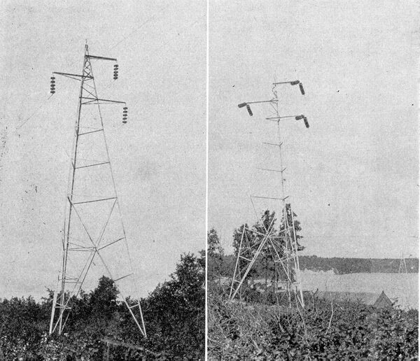
The triangular steel towers used on this line are from 40 ft. to 60 ft. high, and were built by the Aermotor Company, of Chicago. They are spaced about 500 ft. apart. Each leg is anchored to a 3-in. steel angle, 7 ft. 10 ins. long, buried in the ground. The steel angles are enclosed in concrete to prevent corrosion, except for about 50 ins. at the bottom, which is left bare to provide an effective ground for the steel towers. Stranded copper cables with hemp centers, and having a conductivity, equal to No. 2 solid wire, are used for conductors. Figs. 1 and 2 show views of, this line, and also the suspension insulators used. The conductors are hung from cantilever arms, two arms being placed on one side of the pole and one Ion the other.
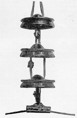 |
| Figs. 3 - Suspension Insulator Assembled. |
The suspended insulators are of the type described by Mr. E. M. Hewlett in his paper presented at the last convention of the American Institute of Electrical Engineers, at Niagara Falls, June 26. Figs. 3 and 4 show the construction of the members of this insulator. Five of these insulators are suspended in series to insulate the line. The diameter of each porcelain link is 10 ins., and the rated voltage that each link will withstand is 25,000, although the links arc over when wet at approximately 65,000 volts each. Fig. 4, while showing the interior construction, also shows the form of petticoat on the insulator used in a horizontal position as a strain insulator at curves and at intervals to anchor the line.
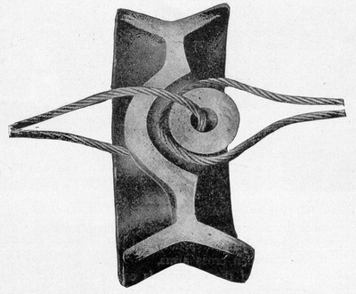 |
| Figs. 4 - Cross Section of Strain Insulator. |
The steel angles to which the links of the tower are anchored were set in concrete at a mixing plant at one end of the line and were afterward transported to points needed. Each complete anchor weighs about 275 lbs. The concrete envelope is elliptical in section, the axes of the ellipse being 4-1/2 ins. and 6 ins., respectively. One 3-in., 4-lb. steel channel and several short reinforcing rods were fastened horizontally near the bottom of each main angle as anchors. These channels and rods also were enclosed in concrete discs; sheet-iron molds being used for that purpose.
