[Trade Journal]
Publication: Electrical World
New York, NY, United States
vol. 50, no. 25, p. 1201-02, col. 1-2
Hydro-Electric Transmission Plant of the
Rockingham Power Company.
BY J. S. VIEHE.
THE site of the hydro-electric plant of the Rockingham Power Company is located on the Yadkin River at a point about 7 miles northeast of the town of Rockingham, N. C., and 16 miles north of the boundary line between North and South Carolina. With a 50-ft. dam, the total power for delivery to customers is 22,500 kilowatts II hours per day, as calculated from government reports. Besides this power there is a large amount available from six to nine months out of the year, which can be used in those industries where the cost of energy is of vital importance and continuous operation for the entire year is not essential. About 11,250 kilowatts is available every day in the year, known as "A" power, and 11,250 kilowatts is available 90 per cent of the time, and known as "B" power.
The market for the energy is located in a very fertile section of the cotton belt served by the main lines of the Seaboard and Atlantic Coast Line Railroads. The various towns are so located as to be economically supplied by two main transmission lines. One of these is to be carried from the power house to Wilmington, a distance of Ho miles, at which point it is expected that 5000 horse-power will be taken as soon as the plant is put in operation, and that this load will increase to 10,000 horse-power in a few years. The route of the line is near and parallel to the Seaboard Air Line track to Wilmington, thus being near all the towns on the railroad. This line is to serve the Scotland Mill 400 horse-power and the Dickson Mill 200 horse-power at Laurinburg, N. C., and about 1400 horsepower to the Dresden, Lumberton and National Mills, at Lumberton, N. C., besides the energy for lighting circuits in these towns, as well as many others located along and in the immediate vicinity of the line. The second line will have its main points of delivery at Rockingham, McColl, Bennettsville, Darlington and Hartsville, furnishing 1400 horse-power to mills in Rockingham, 1600 horse-power to the Marlboro Cotton Mills at McColl and Bennettsville, 2000 horse-power to the Darlington Manufacturing Company, 1500 horse-power to the Hartsville Cotton Mill, and 2300 horse-power to the Carolina Fibre Company, besides energy for lamp and motor circuits in the various towns The majority of the mills are at present driven by steam, for which reason it is being found that there is a considerable demand for secondary, or "B," power, the mills using the latter being so arranged that steam power can be used in case the power company is unable to furnish electrical energy owing to low water.
| |||
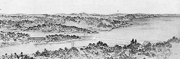
| Fig. 1 - Hydro-Electric Transmission Station of the Rockingham Power Company at Rockingham, N. C. |
The primary, or "A," power is used largely for the supply of public service corporations, who are either unable or unwilling to provide both steam and electrical equipments. A number of mills also take this energy, thus obtaining a reliable supply and enjoying all the benefits of greater production.
The general layout of the development as it will appear when completed is shown in an accompanying engraving from a lithograph which was prepared from plans to indicate the general appearance and relation of the dam, power house, head water, etc. At the point selected for the dam there is a hill on each side of the river, between which the main dam, 1420 ft. long, is carried. The dam, of concrete and large ballast stone, is 50 ft. high, 10 ft. thick at the top and 50 ft. thick at the base. The up-stream face is vertical, the down-stream side being curved to give a long toe. The dam is built in a straight line from shore to shore, and this entire length is used as a rollaway to carry off large volumes of water during freshets. The pondage will extend up-stream about 7 miles, giving an area of water of approximately 2500 acres.
POWER HOUSE.
It will be noted from Fig. 1 that the power house is not located in the main stream, but that the head-water is carried around a hill in a canal to the power house. This canal is a natural one, requiring only a small amount of excavation to give sufficient passage for the water. By this method of development, the power house is protected from floods, and in this particular case a certain amount of head is gained by reason of rapids between the dam and the point where the tailrace enters the river. At the end of this canal is placed the headgate wall, through which the feeders for the various waterwheels are carried. Just below the head-gate wall is the power house, of brick, built on arches of concrete. The power house is designed to contain six three-phase, 60-cycle, 4000-volt, 3000-kw alternators and transformers for raising the potential from 4000 to 60,000 volts. The transformers, as well as all high-tension apparatus, are to be placed in fireproof compartments. All switches are operated electrically from a central bench-board, thus putting the entire control of the station in the hands of one man. The generator room is 260 ft. x 100 ft. and 40 ft. high, and the portion used for transformers, controlling apparatus, etc., is 160 ft. x 75 ft. and 40 ft. high with three floors. Fig. 2 shows the general arrangement. A traveling crane, running the entire length of the building and operated electrically, is to be used in installing the machinery and also in repairing apparatus.
 |
| Fig. 2. - Cross-Sectional View of Power House. |
The transformers are 1000-kw water-cooled units, three connected delta and delta forming a group for each 3000-kw generator. Normally, the station will be operated with transformer-generator units, but a tie-bus is to be provided so that the failure of a certain group of transformers will not necessarily put that generator out of commission.
| |||
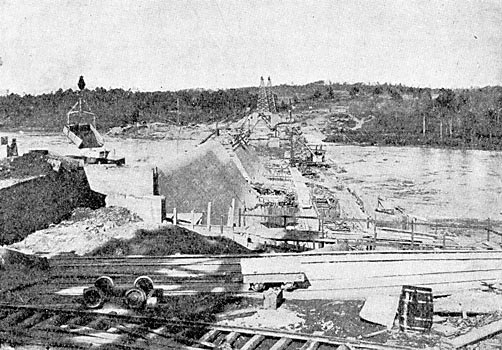
| Fig. 3. - Dam in Process of Construction. |
The exciting current for these alternators is to be derived from three 150-kw, 220-volt generators driven by separate waterwheels.
| |||
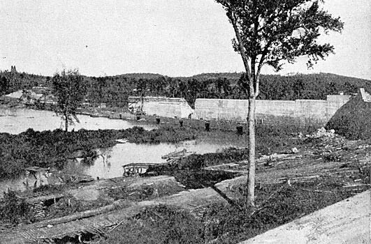
| Fig. 4. - Up-Stream Side of Dam Across the Yadkin River. |
The first installation will comprise the necessary apparatus for three 3000-kw alternators or one-half the contemplated station equipment. All of the apparatus will be furnished and installed by the General Electric Company. The waterwheels are of the inward-flow, turbine type, furnished by the S. Morgan Smith Company, of York, Pa. The governors will be of the Lombard type.
TRANSMISSION LINE.
The transmission system, as at present laid out, comprises a total length of line of 200 miles, being arranged in two circuits as noted, one running to Wilmington, N. C., and the other to Darlington and Hartsville, S. C. On account of the great durability of steel, and the small increased cost of steel towers over wooden poles, it has been decided to use galvanized towers throughout on these lines. The towers are of the standard windmill type, 55 ft. to the highest point, where the ground wire is attached, and 45 ft. to the lowest transmission wire. The towers are anchored to the ground by means of extensions on each post. These anchor pieces are of angle iron with cross pieces at the bottom, and are buried 6 ft. in the ground. The three transmission wires are arranged in a triangle, with 7-ft. sides, two wires being in a horizontal plane and one below. Telephone wires are to be strung on the same towers, 6 ft. below the transmission wires, and will connect the power house and all sub-stations on the high-tension line.
On level ground the towers are to be spaced 600 ft. apart, but in hilly country spans as long as 900 ft. will be used in passing from hill to hill. Great care is being used to insure a certain amount of sag and give sufficient clearance above ground in spans where one support is higher than the other. With the voltage to be used on the line, 60,000 volts, No. 1 copper cable for each conductor is sufficient to carry the electricity. At each sub-station switches are to be placed in the main line by means of which the section of line between that station and the next station can be cut out. By means of these switches, in case of trouble on the line, the section in which such trouble exists can be quickly determined.
A special insulator for this line has been designed by the joint efforts of the company's engineers and the R. Thomas Company's engineers, which, judging from tests, promises to give thorough satisfaction. With this insulator, the ground cable above the transmission wires, and lightning rods on each tower, it is thought that troubles due to lightning will be reduced to a minimum. As it is sometimes difficult to get satisfactory operation of a telephone system when the wires are carried close to 60,000-volt conductors, it has been decided to use a telephone insulator suitable for 10,000-volt work which it is thought will give sufficient insulation to insure good service. At telephone stations a transformer, with secondary grounded, is to be used to protect the user from shocks from the telephone line.
SUB-STATIONS.
In each locality where energy is to be supplied a union substation will be constructed containing transformers, switches and all necessary apparatus for reducing the voltage from 60,000 to a suitable potential for distribution to the various consumers. These buildings are to be thoroughly fireproof in all respects, and are to be provided with oil pump, water pump and means for repairing transformers. On account of the necessary space required for 60,000-volt apparatus, it has been found desirable to arrange the building with two stories, the first containing the transformers, pumps, etc., and the second story containing both high-tension and low-tension switches, the lightning arresters requiring nearly the full height of the building. The electrical apparatus for these stations is to be furnished by the General Electric Company.
CONSTRUCTION.
The building of the complete works requires the placing of 120,000 cu. yds. of concrete and the excavation of 400,000 cu. yds. of material. Of this amount, about 60 per cent of the concrete has been placed and about 30 per cent of the excavation has been done. The method of building the dam has been by means of building crib coffer dams around each section of the dam and carrying the concrete to this section with two cables strung across the river directly over the work. Railroads built on top of the coffer dams on each side of the main dam serve to convey ballast, stone and concrete from the shore. There are also traveling derricks on these tracks which place the concrete and ballast stone. It will be noted that there are two independent methods of building, the cable method and derrick method, which together give a total capacity of 400 cu. yds. per day. In building the dam, sluice ways 12 ft. sq. have been left at certain intervals to carry the flow of the river when the dam is completed the full width of the stream. When it is desired to fill these holes, timber gates will be let down on the up-stream side and the work of filling in with concrete carried on from the down-stream side.
The concrete is placed in wooden forms, which are wired to the interior of the dam and removed after the concrete is
·
·
[Missing text]
·
·
