[Trade Journal]
Publication: Transactions of the American Institute of Electrical Engineers
New York, NY, United States
vol. 15, p. 673-713, col. 1
HIGH-VOLTAGE POWER TRANSMISSION.
BY CHAS. F. SCOTT.
Several years ago an investigation of the conditions and requirements incident to the use of high voltages was undertaken by the Engineering Department of the Westinghouse Electric and Manufacturing Company. In this experimental investigation the size of the apparatus and the conditions of the tests were as far as practicable such as would prevail in actual work.
The transformer, the sine qua non of high-voltage working, received first consideration. A design suitable for large sizes was worked out and tested; then high-voltage windings were made. Attention was next directed to the line insulator.
New phenomena were liable to be presented at higher voltages and it was necessary to determine what they were, also how to meet the requirements which they impose. New forms and sizes of insulators were designed, made and tested to determine the losses which would occur and the limit at "which they would break down.
The luminosity and the hissing sound emitted by the connecting wires of high voltage, suggested a loss which might be an appreciable addition to that over the surface of the insulators. It was found that a very considerable loss of energy took place between the wiresa loss which at high voltages was much in excess of that across the surface of the insulators.
Mr. L. L. Nunn visited Pittsburg at this time and became much interested in this work. He was a pioneer in power transmission, having put in the first large alternating current transmission plant in this country, namely, that at Telluride, Colorado, which was designed by the writer and described by him' at the General Meeting of this INSTITUTE in 1892. It was proposed that this work be taken up conjointly by the Westinghouse company and Mr. Nunn, and prosecuted on a much enlarged scale, by operating the original motor over a high-voltage line. In a report to the Vice President and General Manager of the electric company, dated April 2nd, 1895, the writer said, "The transformers would be arranged to give a line pressure of 10,000, which is to be increased by suitable steps to possibly 50,000 volts. I regard this as an excellent opportunity to make a thorough and extremely important and valuable test of high-tension working under difficult practical conditions, which our company should take up and carry out as fully as possible."
Raising and lowering transformers were made and sent to Telluride, and power for the 100 H. P. synchronous motor was transmitted at voltages far exceeding any which had been previously used anywhere. Exceptional facilities were afforded for observing the practical operation of high-tension working under severe climatic conditions, and for making measurements. The results of the work were so assuring that the Telluride Power Transmission Company has lately installed a plant which is in commercial operation at 40,000 volts and is now making an increase in the plant. This work has been continued on experimental circuits at East Pittsburg, and some measurements have been made at Niagara.
The work which has just been briefly described was an investigation into an unknown field. It has been progressively and systematically carried out and it has determined results which were unforeseen, and which are of both theoretical interest and practical importance.
This present paper describes the more interesting and important parts of this work, and gives the methods by which measurements have been made and the results which have been reached. A number of points of interest and importance are given with regard to long-distance transmission plants now in operation.
HIGH-TENSION TRANSFORMERS.
In 1891 the Westinghouse company furnished transformers for the 10,000-volt transmission to San Bernardino and Pomona. Twenty transformers were used in a set, each giving a pressure of 500 volts and the twenty in series 10,000 volts. This arrangement made the insulation within the individual coils a matter of comparative ease. The insulation between the coils of the high-tension circuit and other parts of the transformer was secured by allowing a space, which was filled with oil.
The first arrangement of transformers for giving from 30,000 to 50,000 volts was made by using a number of transformers, each giving 10,000 or 15,000 volts. The low-tension circuits of the several transformers received current from an insulating transformer in which there were a number of separate coils, each one supplying a separate raising transformer. An arrangement of this kind was used for obtaining the high voltages in the exhibit of the Westinghouse company at the World's Fair. A large transformer was designed in January 1894. The output of 200 w., was many times greater than that of any trans formers which had been made by the Westinghouse company. The transformer was oil-insulated and was cooled by water flowing through a pipe immersed in the oil. This transformer was pronounced a success, and the type was adopted and has been followed ever since as a standard, except that the water-cooling is employed only on the largest sizes.
The transformer was then rewound for 40,000 volts, and a somewhat reduced output. It was operated at this voltage for a short time, when it was found that through an oversight, the insulation between layers was insufficient. In October the high-tension coils were rewound for 60,000 volts and the transformer is still in use after many months of varied service and a considerable period of inactivity.
The making of a single large transformer for a very high voltage naturally involved new difficulties. Above 10,000 or 20,000 volts there was an unexplored and uncertain field in the matter of insulation. Materials which were commonly used at ordinary voltages might have very different characteristics under the new conditions. Tests were made on materials before the first high-voltage transformers were made, and it has been continued. The large high-tension transformer as made to-day was not designed in a week or a month, but it has been an evolution based upon experimental tests and experience in continued operation.
HIGH-TENSION INSULATORS.
After a high-voltage transformer was constructed, the insulator naturally presented itself as a fundamental factor in transmission. The requisites of an insulator for high-voltage work are, that it shall have a dielectric strength sufficient to prevent the current passing directly through the material, that its dimensions shall be large enough to prevent the passage of current over the outside of the insulator to its support, and that the resistance, both of the material and its surface, shall be sufficiently high to prevent undue loss of energy. In addition to these fundamental electrical requirements are those of a mechanical nature involving strength and convenience. These properties must of course be permanent, and not liable to deterioration while in service.
Up to this time very little attention had been given to the manufacture and design of high-tension insulators. There were available for our laboratory tests the glass insulators which we had designed for the 10,000-volt transmission line at San Bernardino and Pomona, California. (See-paper of Mr. G. H. Winslow before the General Meeting of the INSTITUTE in 1895).
A much larger glass insulator was made having the so-called "helmet" form, which was probably the beginning of a type which is now quite common. The large glass insulator presented mechanical difficulties in manufacture, and recourse was had to porcelain. An insulator was designed to be under-hung, the top of the insulator being supported in an inverted cup which was to be, bolted to the under side of the cross-arm. From the bottom of the insulator a pin extended which was anchored in a hole in the insulator and held the wire several inches below the porcelain. The object was to place the wire below the cross-arm so that the snow which might pile up on the cross-arm would not come near the insulator. The wire, moreover, instead of being supported upon the top of the insulator, where it is in connection with an extended wet surface, would be supported from the part of the insulator which is most protected and the dryest [sic] driest.
An interesting evolution then began to take place in the manufacture of porcelain. There were eight or ten steps in this history, in which insulators which were presumed by the manufacturer to be satisfactory were broken down on high-voltage test. Porcelain which presented a beautiful smooth glazed surface was often found to contain internal cracks or cavities which were soon traversed by the current. In other cases 'bits of pebbles or other impurities were found. In still other cases the porcelain was not homogeneous and was not compact, or the material was porous and absorbed a drop of ink almost as readily as a lump of sugar would do. The effect of this work is seen in the improved quality of material now made by certain porcelain manufacturers who benefited by this experience. It may also be remarked that some of the unpleasant experiences with porcelain insulators might have been prevented if similar preliminary tests had been made instead of employing the more expensive and inconvenient method of testing them in commercial service.
The under-hung form of porcelain insulator, however, did not prove successful nor satisfactory. The insulator was heavy and cumbersome, and no satisfactory method was devised for holding the wire. A wooden pin lacks strength, and a metal pin reduces insulation. Moreover, smaller insulators of the ordinary form were found suitable for higher pressures than was anticipated.
Some measurements were made of the losses on the Pomona insulators. Twenty-four insulators were mounted on wooden pins. A wire was run along the tops of the insulators and a second wire connected the pins. The increase produced in the reading of a wattmeter in the primary of the raising transformer when the wires were connected to the high-voltage terminals, was taken as the loss on the insulators. The loss at 25,000 volts was about two watts per insulator. This voltage between pin and wire corresponds to 50,000 volts between transmission wires.
LOSSES BETWEEN WIRES.
The loss over the surface of insulators was quite small, in fact almost insignificant compared with the amount of power which would ordinarily be transmitted. The various displays of energy about high-tension wires, led us to investigate and determine whether this loss was one of importance. In order to measure the loss between wires, eliminating what occurs on the insulators, it was desirable to have a considerable length of wire, to support it without insulators, and preferably to arrange the wires in such a form as to give a considerable loss. Nine wires each 60 feet long were stretched 4" apart in a horizontal plane, and were held in place by strings several feet in length at each end. The wires were No. 19 B and S gauge, 0.036" in diameter. They could be connected in various ways, and any pair or pairs of wires could be omitted as desired.
The power supplied to the raising transformer was measured by a wattmeter placed in the primary low-tension circuit. When the load was placed on the transformer, the wattmeter reading increased, and the amount of increase was taken as the power delivered to the load. This method involves certain errors which will be pointed out further on, but on the whole it gives an approximate and fairly correct indication of the power, and is sufficient to show clearly the general form of the loss curves and a number of interesting characteristics.
The first measurements of this loss are recorded Feb. 26, 1895. The 1st, 3rd, 5th, 7th and 9th wires were connected in multiple to one terminal, and the other wires were connected to the second terminal of the raising transformer; successively increasing voltages were applied.
 |
| Fig. 1. |
The wires began to give a hissing or crackling sound and in the dark began to appear luminous at a little below 20,000 volts. As the voltage was increased the sound became more and more intense, the wires vibrated and became more and more luminous, until at the higher voltages they were surrounded by a coating of soft blue light many times the diameter of the wire. Often there were bright points along the wire, probably corresponding to bits of dust or rough places resembling points on the wire. The large room soon became strongly charged with ozone.
Results of measurements on all wires, alternate wires being connected together to one terminal, and the intermediate wires to the other terminal of the raising transformer, are given in the accompanying Fig. 1. Three curves are given for a frequency of 60 periods per second, or 7200 alternations per minute. Two of these curves give the wattmeter readings for the different voltages, one for the transformer alone, and the other for the transformer and high-tension wires; the third curve gives the difference between the two, and therefore represents approximately the loss on the high-tension wires. Corresponding curves are given of tests made at a frequency of 133. The loss in the transformer is less at the higher frequency, but the loss on the high-tension wires is almost the same for both frequencies. These losses are very small below 18,000 volts, but increase rapidly up to 30,000 volts, which is about the highest pressure used.
As the two sets of tests were made with dynamos having different characteristics, they may not accurately represent the relative effects of the frequencies. The difference due to causes other than the frequency are, however, probably small, so that these tests are correct in showing the general relation between the loss and the pressure, and in indicating that the loss depends little if at all upon the frequency.
 |
| Fig. 2. |
Tests were made with different numbers of wires. In one case the measurements were made with the arrangement described above, in which five wires were connected together and the four intermediate wires were connected to the second terminal of the raising transformer. Two wires at one end were then left off. Two of these were next omitted, leaving three connected to one terminal and two to the other. One of these was left off, leaving the 1st and 3rd wires connected together, and the 2nd and 4th also. The 1st and 9th wires were then connected together, also the 2nd and 8th. As the 1st and 2nd wires were well separated from the 8th and 9th, the mutual effect between them is negligible, so that the loss in this ease may be considered as double that which would be obtained from the 1st and 2nd wires alone. The results of this measurement are plotted in Fig. 2. The points for both loss and current fall on a straight line and indicate that each additional wire causes a definite increase.
Measurements made upon wires at greater distances show that the action is considerably less as the wires are separated. The loss is approximately the same at 28,000 volts when the wires are 4" apart that it is at 30,000 volts when they are 16" apart. The loss for a distance of 8" is intermediate.
Other measurements were made, but nothing of further importance was developed. It is interesting to note that within a few days of the first measurements the general characteristics of this loss were determined, namely, that the loss between wires increases rapidly after a critical voltage is reached, that the loss is practically independent of the frequency, that it is much less as the distance between wires is increased. When a loss of 1200 watts was obtained on a total length of 540 feet of wire at only 30,000 volts, the important bearing of this phenomenon upon transmission became very evident. The tests were stopped as preparations were begun for the continuation of the work at Telluride.
TRANSFORMERS AT TELLURIDE.
The original Telluride plants operated at 3000 volts. Both the generator and the synchronous motor were wound for this pressure. Two transformers were furnished for the high-voltage tests, one for raising the generator voltage for transmission, and the other for lowering the voltage for the motor. The windings were connected with a number of terminals by which the tension voltage could be varied over a wide range up to 60,000 volts.
 |
| Fig. 3. |
Coils of similar shape were placed side by side in what is known as the "parallel" form of construction. Each coil had many layers of wire and but few turns per layer, thus securing a small difference of pressure between consecutive layers. The high-tension winding was divided into four similar coils, each designed to give a maximum of 15,000 volts. The individual coils could be differently connected, either in series or in multiple. The low-tension coils were five in number and were provided with loops, by which the number of effective turns could be varied. Three low-tension coils were placed between two pairs of high-tension coils and the two remaining low-tension coils were placed on the two ends. Between the low-tension and high-tension coils metallic shields were placed, which were connected to the ground for protecting the low-tension circuit from danger in case of accidental contact with the high-tension circuit, and also for screening the low-tension circuit from electrostatic induction from the high-tension windings. The transformer was immersed in a case containing oil. The iron and the case of the transformer as well as the shields between the coils were connected to the ground.
There was also an auxiliary transformer whose primary was connected across the generator terminals while its secondary was placed in series with the circuit to the raising transformer, thus either raising or lowering the generator E. M. F. as desired. The secondary had a number of 'steps so that the voltage could be varied at will.
THE TRANSMISSION LINE.
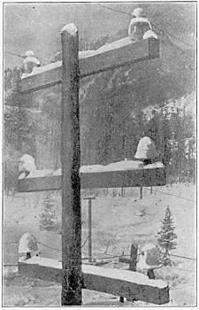
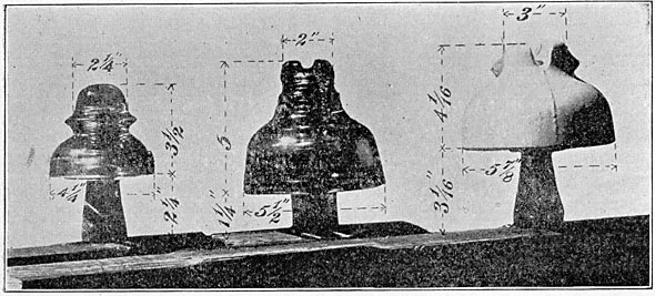
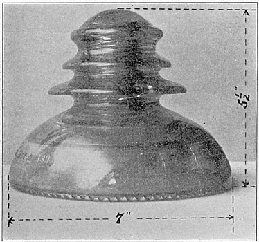
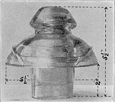
The line extends from the power station near Ames, which is a few miles from Telluride, Colorado, to the Gold King mill. The line passes over an exceedingly rugged country and has a total length of nearly 2 1/4 miles (11,720 feet). There are 62 poles, each carrying three cross-arms, the upper being about 26 feet from the ground. Each cross-arm carries two wires supported by insulators which are designated as follows:Large glass, small glass, porcelain. (See Figs. 4 and 5). The large glass insulator is the same as that used on the circuit in the San Bernardino and Pomona plant. The total height is 5" and the maximum diameter 5 1/2". The bottom of the insulator stands 1 ¼" above the cross-arm. The porcelain insulator is 4-1/16" high and 5-7/8" in diameter. The bottom is 3-1/16" above the cross-arm. The small glass insulator is 3-1/2" in height, 4-1/4" in diameter and stands 2-1/4" above the cross-arm. This insulator is triple petticoat; the other two insulators are double petticoat. The circuits were strung with galvanized iron wire 0.165" in diameter, which is No. 8 B. w. G., and about No. 6 B and S gauge. Later the circuit on porcelain insulators was changed to No. 6 B and S copper wire 0.162" in diameter. The measured resistance of one of the iron wire circuits was 66.25 ohms at -7 deg. C.
| |||
| Fig. 4. 50,000 Volts on Large Glass Insulators (Upper Cross-Arm) and on Porcelain Insulators (Lower Cross-Arm.) |
| |||
| Fig. 5. Insulators Used in High-Tension Tests at Telluride. |
THE LIGHTNING PROTECTION.
The lightning protection was laid out by Mr. A. J. Wurts, who previous to this time had spent some months at Telluride, determining the requirements for protecting the 3000-volt circuit. The protection consists of choke-coils and spark-gaps of non-arcing metal, as described by Mr. Wurts in his paper before the INSTITUTE, March, 1892.
In each line ten choke-coils were placed. Unit arresters, each consisting of seven non-arcing metal cylinders and having six spark-gaps, were connected as is shown in Fig. 3.
RUNNING TESTS AT TELLURIDE.
The first tests were qualitative rather than quantitative. It was uncertain what phenomena might accompany the operation of a long line at high voltage, and the pressure which could be used on the insulators was a matter to be determined. The first thing was to find what would work; measurements could be made afterwards. A high voltage was placed on the transmission line, sometimes transmitting no power and at other times operating the 100 H. P. synchronous motor. In December 1895, the motor was operated at 25,000 to 33,000 volts for several days. In January 1896, 45,000 volts was used continuously for over a week, and beginning with the latter part of March a continuous run of 37 days was made at 50,000 volts. "Some very severe conditions of weather were encountered during this time, very high gales of wind prevailed, the air was filled with clouds of dust, part of the time the snow which fell was quite damp and during the last few days of the run there was some rain. At this voltage the wires were plainly visible at night and the characteristic hissing of high-tension currents could be heard several hundred feet. No lightning arresters had been installed up to this time and the cause of the shut-down was damage to the raising transformer, caused by lightning. Lightning arresters were installed. The lightning season commenced about June 1st. During the latter part of June lightning discharges over the arresters were very frequent. At this time we were limited to a running voltage of about 34,000 volts, as there were not enough arresters to permit of increasing the voltage. No trouble whatever was had with the lightning protection. Discharges were frequently seen crossing the arresters and during two or three days in the early part of the season discharges occurred at intervals of a few seconds for several hours. Enough arresters were afterwards obtained to run at 45,000 volts, but the lightning discharges were much less frequent."
Some measurements upon the line were made by determining the power to the raising transformers when the lines were connected and when they were disconnected. These measurements showed that the loss due to the line is small, below 45,000 volts, but increases rapidly when about 50,000 volts is exceeded, and reached 16.4 K. W. at 59,000 volts. The results up to 52,000 volts are given in curve 2, Fig. 9. Curve 1 in this figure is the loss on the same circuit measured a year later by a different observer using a different method. At the maximum loss shown, there is a difference of only 8 or 9 per cent. in E. M. F. for the same loss on the two curves.
The record of the operation of this line at 50,000 volts for over a month is of very great interest, as it is a practical demonstration of the feasibility of operating a line at 50,000 volts, a pressure four or five times as great as any which had been in general commercial use. Mr. V. G. Converse had been up to this time closely associated with this work. He had much to do with the design and construction of the high-tension transformers and insulators, tests upon losses in lines made at the Pittsburg laboratory and the tests at Telluride.
MEASUREMENTS AT TELLURIDE
The work at Telluride was then taken up by Mr. R. D. Mershon. The facilities for experimental work were increased and instruments were provided for carrying on the tests. Mr. Mershon found peculiar difficulties in making exact measurements of the power to the circuit. A wattmeter in the low-tension circuit of the raising transformer led to errors under time conditions which prevailed. Some very able and painstaking work was displayed in detecting the error and overcoming it with the facilities at handand the facilities were none too plenty in the heart of the Rocky Mountains for making measurements which would tax the resources of almost any laboratory. The apparatus used introduced a disturbing influence in the circuit, which, however, could be measured and eliminated. On the other hand, a wattmeter for measuring power on a high-tension circuit must accommodate a very high voltage and a very small current. As the charging current to an open line is usually very large in proportion to the loss current, the error of the instrument is very sensitive to slight variations of phase in the shunt current. A description of the instruments and the methods used are given in an extract from the report of Mr. Mershon which will be found at the end of this paper in Appendix A. The results of the measurements and the conclusions are given partly by extracts from Mr. Mershon's report, and partly in abstract.
RESULTS OF MEASUREMENTS.
"The results of measurements taken are embodied in curves.
"In every ease the measurements were taken upon an open-circuited linein no ease upon a line which was transmitting power. The line losses obtained are therefore a combination of those occurring between the line wires and the very small I2 R loss in the wire itself due to the charging current of the line.
"Measurements taken with the Weston wattmeter include the loss in the high-tension coil of the power transformer due to the currents applied to the line. This loss is in general small and in the following curves corrections have not been made for it. Curves taken with the Thomson wattmeter require no such correction.
"There is an additional correction which may be made in the case of those curves whose voltages were obtained from the raising transformer. This correction arises from the fact that the action of the capacity current taken by the line, in connection with the series reactance of the transformer supplying it is such as to make the voltage impressed upon the line somewhat greater than that obtained by the ratio of the transformer winding. The measurements taken to determine the amount of the error in voltage show it to be small.
"There were two generators used. One was that regularly running, and supplying power to the power circuits of the Telluride Power Transmission Company. It is a 600 K. W., 22-pole, quarter-phase machine, delivering 500 volts at a frequency of 60, or 7200 alternations per minute. Its armature is of the slotted type and is wound with copper bars. In the notes this generator is designated as 'Slotted Armature.'
"The other generator is one whose field is that of the 100 K. W. toothed armature machine, originally sent out as a part of the first Gold King transmission plant. It has twelve poles and as originally run operated at 3000 volts and 10,000 alternations. There are two armatures for this machine; a surface wound armature, designated as 'Smooth Armature,' and a toothed armature designated as 'Toothed Armature.' "
 |
| Fig. 6. |
Comparison between Insulators. A set of measurements was made for comparing the loss on the three circuits supplied respectively with large glass, small glass and porcelain insulators. The curves are very nearly identical and correspond very closely with the right hand curve in Fig. 6. "There was a heavy wet snow on the ground and the cross-arms at the generating station, and more or less snow all along the line; that at the further end being drier than at the generating station. There was more or less snow falling during the measurements, and this accounts for a wide variation of the points taken at the high voltages, as falling snow renders the wattmeter reading very unsteady, the unsteadiness being such as one might expect if from time to time there was a discharge between the wires. This unsteadiness does not seem to be as great in the case of falling rain as in the case of falling snow."
 |
| Fig. 7. |
 |
| Fig. 8. |
Loss and Distance Between Wires. A series of measurements was made to determine the connection between the loss and the distance between wires. "As at that time it had not been fully demonstrated that the loss was not affected by weather conditions except there was precipitation, changes in distance between wires were made upon one circuit, while the distance between wires On another circuit was maintained always the same, and the latter was used as a reference circuit when a change in loss was obtained."
The several curves have been plotted together, due correction being made for the slight difference in the loss in the reference circuit, which probably resulted from slight differences in the precipitation when the curves were taken. The distance between the wires in the several tests was 15, 22, 35, and 52 inches respectively. The results are shown in Fig. 6. It will be noted that the loss is much greater when the wires are close together and that the curve begins to ascend at a lower voltage.
Comparison of Wattmeters. The loss curves in Fig. 7 were taken on one of the circuits, first, with the Weston wattmeter and then with the Thomson wattmeter. The Weston wattmeter was not in circuit when the measurements with the Thomson wattmeter were taken. As an additional check, the readings were taken on each of the wattmeters of the loss occurring in the shunt resistance, of the Thomson wattmeter the results were in practical agreement with each 'other and with those obtained by calculation. The discrepancy in the results obtained on the two instruments when measuring line loss will be referred to later.
Loss on Insulators. A set of comparative readings was taken on one of the circuits and on a dummy circuit, identical with the main circuit, as regards kind and number of insulators and the size of wire, but only 60 instead of 11,720 feet in length. The results show that the loss on the two circuits is practically identical up to about 50,000 volts, which is the part of the curve below the bend. The losses agree closely with those shown in Fig. 6. At higher voltages the loss on the dummy circuit increased slightly, indicating that the loss was of the same nature as that at a lower voltage. The agreement of the loss on the two lines at low voltage (i. e., below the bend in the loss curve) indicates that this loss was over the insulators. The great increase in loss on the long line at high voltage indicates that the loss was due, not to the insulator, but to the line.
 |
| Fig. 9. |
Resistance and Reactance in the Circuit.Measurements were made with resistance between the generator and the raising transformer, then with reactance and then with neither resistance nor reactance. The results are shown in Fig. 8, and indicate a different condition, depending upon the character of the circuit, supplying the current. It was presumed that this difference arose from a modification of wave form of the E. M. F. applied to the line.
 |
| Fig. 10. |
Wave Form and Loss.Measurements were made upon the wave form and the corresponding losses when different generators were used and different circuits were connected. In one test an armature giving nearly a sine wave was used which delivered current at 30 cycles. Measurements were made upon one circuit only, and then upon two circuits in multiple. The current find the loss are both given in Fig. 9. The wave form for no load and for both conditions of load are given in Fig. 10. The current taken by the two circuits in multiple is twice that to a single circuit. The variation from a straight line in one of the current curves is due to a change in wave form as the voltage is increased.
 |
| Fig. 11. |
 |
| Fig. 12. |
The loss for the two circuits in multiple is about twice as great as for one circuit at low voltages, but it is less than that for one circuit at high voltages. Referring now to the wave form taken at high voltage, it is seen that the wave form for the two circuits in multiple has a lower maximum than that for one circuit alone. The reduced loss on the two circuits is undoubtedly due to the different wave form when both circuits were connected. The distortion of the wave form is due to the reaction which the leading current produces in the generator and transforming apparatus.
Wave forms were also taken on the slotted armature giving 60 cycles. The wave forms are given in Fig. 11. The conditions are similar to those just described, in that a single circuit produces a wave having a much higher maximum than that produced when two circuits are run in multiple. The losses (which are not shown) bear the same general relation as that in the last case, namely, the loss with two circuits is greater at low voltage and at the high voltage is less than that on a single circuit.
A wave form was taken upon the toothed armature both at no load and also when supplying current; to one of the circuits. These are shown on Fig. 12. This wave differs radically from a sine wave at no load and is greatly distorted when supplying a leading current. In the no-load wave the value of the fundamental is 72.5 per cent.; the third harmonic 21.6 per cent.; the fifth harmonic 4.8 per cent. The corresponding loss is given in curve 1, Fig. 9. The distorted wave makes the Thomson wattmeter read too high, especially at the lower E. M. F'S.
OTHER OBSERVATIONS AND TESTS.
"A series of observations was taken extending over a period of thirty-three days, to determine whether there was any connection between the loss occurring on the lines and the variations in weather conditions. Three readings were taken each day. They were, in addition to the wattmeter readings, readings for barometric pressure, temperature, humidity, wind direction and wind velocity. The weather observations were taken simultaneously at Ames and the King, using sets of weather instruments furnished by the United States Weather Bureau. The range of these observations is shown in a table given below, in which maximum and minimum refer to the maximum and minimum results obtained at any time during the thirty-three days over which the measurements extended:
 |
"If there, was any variation in the loss on the lines for this range of weather conditions, it was so small as to be inappreciable. The results of all measurements taken during this work seem to confirm the fact that the only weather condition whatsoever which affects the loss to any practical extent is that of precipitation. The loss seems to bear some relation to the size of the particles precipitated, being greater for a fall of snow in which the flakes are large than one in which the flakes are small.
"If the power transformers used, the series reactance was comparatively small because of the subdivision of the coils. A change in the condition on the line as regards loss occurred when the Weston wattmeter was placed in circuit. This was detected by measurement upon the Thomson wattmeter, both when the Weston wattmeter was in circuit and when it was not. Moreover, the lines hissed when the voltage is 55,500 and the Weston wattmeter is out of circuit, but when the Weston wattmeter is thrown into circuit the hissing ceases, although the voltage rises to 57,700. The hissing sound is a characteristic of high-voltage lines and begins at the bend in the loss curves. It always accompanies luminosity of the lines.
"Along with this change there was another phenomenon not previously mentioned. This was a discharge which took place from time to time between the terminals of individual choke-coils. The discharge would occur sometimes between the terminals of one choke coil and sometimes simultaneously on two or three of the choke coils. These discharges made considerable noise, sounding very much like a pistol shot, and could be heard at a considerable distance from the transformer house. As the choke-coil terminals are distant from each other about 8 1/4", it is not thought that this discharge took place through the air, but over the surface of the wood enclosing the choke-coil. The discharge, however, left no mark on this surface. Simultaneous with these choke-coil discharges one could hear, if standing under the line some little distance from the transformer house, a slight snap which seemed to be a phenomenon rather of the whole line than of any particular spot in it. Sometimes there was a corresponding snap over the lightning arresters. As the lightning arresters make more or less noise at all voltages, this snap over them may have been present at all times, hut in some eases not sufficiently well marked to be heard above the continued hissing of the lightning arresters.
"After the preceding results had been obtained, the two power transformers were connected up with their high-tension windings in series, the point of connection between them being grounded, and with their low-tension windings in multiple. With this arrangement voltage was impressed on one of the circuits, power being supplied by the smooth armature at 7200 alternations. The voltage was run by means of the machine field to 90,000.
"As the power taken by the lines at this voltage overloaded the motor used to drive the generator, a span was cut out of the circuits at a little distance from the station, leaving about 500 feet of wire in them. The voltage was run up to 133,000 volts and held there for some minutes; but the current finally jumped from the outside terminal of each transformer to the iron, smashing the heavy glass tube with which these terminals were insulated."
DISCUSSION OF RESULTS.
The following is taken from Mr. Mershon's discussion of the results of his tests.:
"There is evidently a certain critical voltage at which the loss occurring between wires begins to increase very rapidly; indeed, it seems as though there might be something of the nature of a polarization similar to that which occurs in the case of an electrolyte; that there is something of this nature in the case of air or other gases subjected to an electrostatic stress is well known, and it has been taken as an explanation of the fact, that in the experimental determination of sparking distances in air, a certain minimum potential is necessary to establish an arc, no matter how small be the sparking distance. Also, Varley has done some work on tubes containing gases. This work was done with a series of Daniell's cells yielding 300 to 400 volts. The voltage was impressed upon electrodes sealed into the tubes. Ile established the following facts:First, that each tube required a certain potential to leap across; second, that the passage for the current having been once established a lower potential was sufficient to continue the current; third, if the minimum potential which would maintain a current through the tube be P and the voltage varied to P plus 1, P plus 2, etc., to P plus N, the current will vary in strength as 1, 2, 3, etc., N; P always meaning the lowest value at which the current will continue, and is less than that at which the current starts.
"If such a condition of affairs obtains in this case, the loss curves of the preceding sheets must be made up in two parts, one the loss over the insulators and cross-arms, the other the loss occurring through the air. The first part of the loss curve up to or near the point where the abrupt bend begins, must be the loss over the insulators and-cross-arms alone; beyond the point where such a bending occurs, the loss curve must be made up of a combination of the two losses referred to.
"If the action which takes place in air is similar to that obtained by Varley, we might expect that both (1) the position of the critical bend on the loss curve and (2) the law which the loss follows above the bend, would be affected by the form of the E. M. F. wave impressed upon the line for the former (1) must depend, not upon the mean square of the voltage impressed upon the line, but upon the mean square of that portion of the F. M. F. wave which is above a certain critical voltage, and the latter (2) must depend upon the form of that portion of the E. M. F. wave above a certain critical voltage because, as Varley shows, the minimum voltage at which this peculiar loss begins, differs slightly from the minimum voltage at which it will continue after the action has been established. If it were not for the latter consideration it would be comparatively easy to determine the equation for such loss at least in the ease of a pure sine wave, and it might be that there is a sufficiently small difference between the voltage at which this loss will begin and the voltage at which it will discontinue for such an equation to hold practically. That the loss depends upon the maximum value, if not upon the form of the E. M. F. wave, is shown by several of the loss curves in connection with their corresponding wave forms. This is particularly noticeable in one or two cases where the loss on two lines in multiple is less than that on one line, and although some of these comparisons will have to be made between curves taken on the two different wattmeters and are, therefore, not strictly comparable, they may be compared after such correction as is mentioned below in discussing the wattmeters. In any case the curves are comparable, qualitatively, as regards the position of the critical point.
"It might be objected that the results are rendered questionable by the curves in Fig. 7. The Curves were taken under presumably similar conditions, except that one was obtained by means of the Thomson wattmeter and the other by means of the Weston wattmeter. This discrepancy is attributed to a charging current passing through the shunt resistance of the Thomson wattmeter. That the amount of capacity current necessary to produce the discrepancy is small, appears upon the following considerations:--In one ease the loss obtained upon a circuit at 38,000 volts when using the Weston wattmeter is 90 watts, and under the same conditions, but using the Thomson wattmeter, the loss is 215 watts. The difference in the loss obtained by the two wattmeters is therefore 125 watts. The current is about 0.25 of an ampere. Now, 0.25 of an ampere if in step with the E. M. F. would give on the Thomson wattmeter at 38,000 volts a reading of 9500 watts; therefore the capacity current through the shunt resistance necessary to produce the discrepancy of 125 watts is 125 divided by 9500, or about 1.3 per cent. of the current in the shunt resistance. The shunt resistance has a value of 1,202,300 ohms; at 38,000 volts the current through it would be about 0.032 amperes; 1.3 per cent of this, or 0.00416 amperes is that required to produce the discrepancy noted. In further support of this method of accounting for the discrepancy, the results obtained at different numbers of alternations using the Thomson wattmeter show a variation for different numbers of alternations of the losses below the bend in the loss curve, and which are thought to occur over insulators and cross-arms. There should be no variation in such loss for a variation in frequency.
"Any discrepancy occurring in the Thomson wattmeter by reason of a capacity current in its shunt resistance will be affected to a greater or less extent by change in the wave form.
"It is believed that all the phenomena connected with this Work may be studied in a tube which has been partly exhausted. The work could then be done with comparatively low voltage and using direct current which would much simplify the measurements. The contents of the tube might be partially rarefied air or other gas, as the action would undoubtedly be similar in all gases. With such a tube might be studied the law of variation in distance and form of electrodes, also in material and surface of the same.
RESUME AND CONCLUSIONS.
"It is undoubtedly true that the loss is made up of a loss over insulators and a loss between wires, and that the latter is the Only loss worth considering.
"The loss between wires is not affected by any atmospheric conditions except precipitation. This statement of course must be taken as applying to such a climate as that in which the measurements were taken. The lines were seldom in fogs or clouds, and when they were, or when rain was falling, the moisture was of the purest. Near cities the loss would be undoubtedly much greater than that shown in these curves, because of the impurities both in solution in the moisture of the atmosphere and in suspension.
"There will be for a given transmission a certain economical voltage, because while an increased voltage, with a given line. wire, will reduce the loss in this wire by decreasing the transmission current it will also increase time loss between the wires.
"It is believed that attention to wave form is very important. The sine wave is undoubtedly the best as giving a stable form, and because of superior results with all kinds of apparatus. A flat wave would of course give less loss, but would not be stable, and as the nearest practical approach to a sine wave will not he perfectly stable but will still contain some harmonics, it will be of advantage to keep the series reactance of the transformers and generators as low as possible.
"It is believed that 40,000 volts is perfectly conservative and safe as regards loss between wires for any ordinarily good wave form, and in a climate such as that in which the measurements were taken, e., where the air and precipitated moisture are practically pure, 40,000 volts comes well below the bend in the loss curve even under the worst weather conditions.
"I can see no advantage of porcelain over glass, unless it be that of superior mechanical strength. The latter is rather a doubtful advantage. The ball from a heavy calibre rifle or revolver such as are used in the western country will smash any insulator whether glass or porcelain. Porcelain offers a more tempting mark, being white. As to hygroscopic properties, no difference could be discovered so far as these measurements were concerned. It will make little difference under running conditions whether the insulator be hygroscopic or not, as the small amount of power necessary to keep the surfaces dry will he insignificant. I say under running conditions, because in starting up a 'cold' line there is danger of break-down if current is put on suddenly at full value, instead of being raised gradually. As far as the resistance to piercing is concerned, glass is just as good practically at least as porcelain. It needs no electrical test to pick out a good glass insulator, which is one advantage of glass over porcelain.
"To sum up, glass insulators are cheaper, lighter, more easily tested and less likely to he shot at than porcelain; on the other hand, they have less mechanical strength.
"In every case, in my experience, where a breakdown has occurred, it has been on a cross-arm which was 'wind shaken' and weather cracked,' the current following the cracks. This leads to a curious result. The mark of the current will be on surface of the arm for five or six inches, then disappear from the surface altogether for some inches, then reappear, etc. On cutting open the arm one sees how the current has followed the best path, dodging in and out. Rain and moisture probably settle towards the cracks, carrying salts from the body and surface of the wood. This forms a path of low resistance, especially in wet weather. For this reason I have in the plant of the Colorado Electric Power Company taken particular pains in treating both pins and crossarms. The cross-arm treatment is such as fills all cracks and fissures as a section of the wood shows.
"This report would be incomplete without an acknowledgment of the assistance rendered in the work by the engineering force of the Telluride Power Transmission Company. headed by Mr. P. N. Nunn. Especial credit should be given Mr. A. L. Woodhouse for his faithful work and constant perseverance in the face of great discouragement."
HIGH-TENSION TESTS AT EAST PITTSBURG.
Laboratory tests and measurements on a small scale cannot take the place of tests under the conditions of. practical service, such as those at Telluride. There are, however, many important elements which may be determined by laboratory measurements.
A high-tension line for testing insulators and making measurements upon the losses between wires was erected at the East Pittsburg factory in the fall of 1897. A number of the tests which have been made are here recorded.
(1) A test was made to determine whether the wave form of time charging current to the line was similar to that through a resistance, or whether it was modified by the loss component, the loss occurring only at the higher part of the E. M. F. wave. The current to the high-voltage line, at pressures varying from 30,000 to 110,000 volts, was passed through a coil possessing high self-induction. The E. M. F. upon the coil was measured by a voltmeter. The E. M. F. was also measured when a current of equal strength was passed through the coil, the line being short-circuited and a low E. M. F. applied. It was found that the voltage upon the coil was the same, within a small error of observation, in both cases, showing practically no difference in the wave form of the current under the two conditions. The current was from an armature giving practically a sine wave.
The charging current to the line was measured under several different conditions when the current was obtained from a generator giving practically a sine wave. The results of measurements were compared with the currents as calculated by the theoretical formula. The last measurement in the table was made upon the Niagara-Buffalo line, with current from a Niagara generator, which differs slightly from a sine wave.
COMPARISON OF MEASURED AND CALCULATED CHARGING CURRENT TO PARALLEL WIRES. LENGTH, ONE MILE-10,000 VOLTS.
 |
A table giving the calculated charging current for a number of conditions will be found in Appendix B.
(2) The fall of potential around the wires was noted by tests made with spark-gaps. The wires 48" apart were connected to the high-voltage terminals and a spark-gap was placed between two idle wires also 48" apart, placed about 21" below the first wires. A spark-gap consisting of brass terminals with a 1/4" radius was placed between the two idle wires. When the gap was 1/32" the sparking began when the E. M. F. from the raising transformer was 26,000 volts. A gap of requires an E. M F. of 2,200 volts to produce sparking. When the spark-gap was made 8/32" (equivalent to 12,000 volts) the sparking began at 103,000 volts from the raising transformer. At intermediate points there is a fair proportionality between the spark-gap and the E. M. F.
 |
| Fig. 13. |
In another test a spark-gap was placed between one of the idle wires and the adjacent wire of the live circuit. When the spark-gap was 1/8" (equivalent to 6,000 volts) the spark passed when the E. M. F. was 17,500 volts, and when the spark was made 1/4" (equivalent to 12,000 volts) the sparking began at 33,000 volts. When the gap was 3/8" (equivalent to 16,000 volts) sparking began at 41,000 volts. When the gap was ½" (equivalent to 20,000 volts) sparking occurred at 49,000 volts. The E. M. F. did not differ greatly from a sine wave. These tests have an important bearing in connection with the running of telephone and other circuits adjacent to high-potential wires. It is essential that the wires of a high-potential circuit be spiraled so that each wire sustains the same relation as every other wire to the second circuit, in order that the effects of static induction may be neutralized.
(4) The effect of the size of wire upon the loss was investigated by running a pair of No. 28 brass wires 0.0126" in diameter and then replacing it by large rubber-covered wires. The rubber-covered wire was No. 7 n and s. gauge 0.144" in diameter ; the outside diameter of the rubber covering was 0.3" and the diameter over the braid was 0.35". In each case measurements were made upon another circuit which was unchanged during the different tests, and thus served for comparison. The results of these tests are shown in Fig. 13, which also gives the conditions when one fine wire and one wire of larger size, No. 8 B and S, constituted the circuit. This comparison shows the very marked increase in loss when the fine wire is used. The loss is greatly decreased when the rubber-covered wire is used. The loss on the rubber-covered wire, however, increased considerably after the voltage had been raised and the rubber had broken down, thus permitting the current to pass freely to the outer surface of the insulation. It is quite probable that the loss would increase as the insulation became defective, until it was nearly equal to that of a wire having the same total diameter.
The measurements on wires of different sizes given in Fig. 13. are qualitatively correct, although some of the readings on which the curves are based were quite small, so that the absolute values may not be exact.
(5) The effect of the current in drying the surface of the insulators was illustrated in a test made during a rain. Upon applying 45,000 volts to a circuit the wattmeter indicated 116. After four minutes the. deflection had decreased to 72, the current remaining the same. The E. M. F. was then increased to 60,000 volts, the wattmeter deflection increased to 155, and at the end of three minutes it had fallen to 138. The current was one-third greater than at the lower voltage, but remained constant while the -wattmeter changed. The rain continued during the test, which shows, therefore, that the condition of the insulator is materially improved by the presence of the current.
(6) It was noticed that when there was a break-down upon the line and the current passed suddenly between wires over the surface of the cross-arm that there was a sparking between the terminals of the ammeters in the high-tension circuit across the surface of the instrument. This was further investigated by placing in circuit a coil of low resistance through which one ampere would be sent by about 1 1/2 volts at a frequency of 125. A spark-gap was placed in shunt to this coil. A 2" spark-gap was also placed between the line wires. The voltage of the primary was gradually raised until at 35,000 volts the current passed across the spark-gap between the line wires. A spark also passed across a gap of 3/8", shunting the small choke-coil. This test shows the remarkable suddenness of the rush of current, when the short-circuit occurs due to the breaking down of the spark-gap on a high-voltage circuit. This phenomenon was observed by Mr. Mershon in choke-coils used in connection with lightning arresters at Telluride.
Running tests were made on four lines in multiple at high voltages. Each line consisted of two wires 1,040 feet in length held by 26 insulators. The insulators were of various types of glass and porcelain, some of the ordinary form and some under-hung. For hours at a time 100,000 volts or slightly more were -kept upon the line. For about six weeks voltages ranging from 70,000 or 80,000 to 100,000 volts were kept on the lines for about eight hours a day. When there was rain the line would short-circuit and the voltage had to be reduced. During a driving rain storm 48,000 volts was kept on the lines, and it may have required a considerably higher voltage to have caused short-circuiting.
(7) A high-tension wattmeter similar to the Thomson wattmeter at Telluride was used. To correct the wattmeter for the errors caused by charging current in the shunt resistance, a condenser was placed in parallel to the shunt circuit of the wattmeter. This condenser should be so adjusted that, the current through the shunt circuit of the wattmeter is the same that it would be if there were no condenser and the shunt resistance had no capacity. This permits the capacity current in the circuit to be shunted round the wattmeter by the condenser. The condenser in shunt to the wattmeter was capable of adjustment, and by varying its capacity the deflection could be made positive or zero or negative when current was delivered to a constant load. The proper adjustment was made by taking a comparatively low voltage, at which the charging current was very high in comparison with the loss, so that the loss was nearly negligible, and adjusting the wattmeter to indicate zero. At higher voltages, when there was a considerable loss, the error with this adjustment would be inappreciable. Certain variations with temperature and humidity were noted which would be explained by a variation in the capacity of the resistance, causing a variation in the charging current to the shunt circuit of the wattmeter. The high resistance for the shunt circuit was wound upon fuller-board plates containing brass stiffening pieces. Tests were made upon individual plates by measuring the capacity between the wire and the supporting strip of brass, and it was found that the capacity and the insulation resistance both varied with the amount of moisture in the fuller-board insulation. In order to prevent variations of this kind, subsequent resistances were wound upon glass plates, which seems to be a very satisfactory form of construction.
TESTS AT NIAGARA.
Some measurements have been made upon the Niagara-Buffalo transmission line. There are two circuits of three wires each, one of which was in service and the other was available for tests. Each circuit consists of three cables each of 350,000 C. M., approximately 0.7" in diameter. The cables are run on porcelain insulators, and are on the same cross-arm. Adjacent insulators are IS inches apart and the circuit is spiraled, so that each of the three wires occupies the middle position for a third of the distance. Current from one of the 5000 H. P. generators was applied to the line through a raising transformer, by which the voltage can be increased by small steps to 100,000 volts. This transformer is part of a high-tension testing outfit which is described by Mr. C. E. Skinner in the Electrical World, March 5, 1898. The wattmeter is a Thomson inclined coil instrument with a high resistance shunt of german silver wire wound on glass plates. The ammeter is a Thomson inclined coil instrument, connected directly in the high-voltage circuit.
Measurements were made between the various pairs of wires, i.e., 1 and 2. 2 and 3 and 1 and 3; the current was found to be. practically the same in each case; the loss on one, of the circuits was slightly greater than that on either of the other two, on which the losses were about equal. The accompanying curve shows the measurements of current when two wires were connected and the measurement of loss; the latter measurements were-made upon one pair of wires up to about 26,000 volts and then upon a second pair. The results are given in Fig. 14.
 |
| Fig. 14. |
On another day measurements were made of the resistance between each wire and the ground, and corresponding measurements of loss were made by placing the high potentials between each wire and the ground. The measured loss was somewhat greater than the loss calculated by using the E. M. F. and the measured resistance. In these measurements, at voltages from 13,000 to 23,000 volts, the power factor calculated from the current and wattmeter measurements, varied from about 4% to 6%, so that a very small charging current in the wattmeter would produce a considerable error in the reading.
 |
| Fig. 15. |
Some measurements were made upon a pair of fine wires, in which the wires were placed at different distances apart. No. 31 B and S gauge spring brass wire 0.0089" in diameter was used. The length of the parallel wires was 744 feet. They were suspended by light strings successively at 6" apart, 14" apart, and about 25" apart, the distance varying from 24" to 27". The wattmeter readings are given in the curves in Fig. 15. The power factor of the measurements made above 100,000 volts is about 95%, and is over 80% above 70,000 volts. There can be but little error in the wattmeter due to charging current in the resistance at these power factors.
The measurements on the Buffalo line were made by the writer. Those on the fine wires were made by Mr. E. M. Tingley, who conducted the tests at East Pittsburg, and rendered valuable assistance in the preparation of this paper.
POWER TRANSMISSION PLANTS IN OPERATION.
Beginning with the plant at San Bernardino and Pomona, which began operation in 1892, using 10,000 volts and transmitting 30 miles, a constantly increasing number of plants have been installed operating at 10,000 or 15,000 volts. In some cases there has been little or no trouble experienced with the transmission lines, while in other cases the experiences have been less satisfactory. The principal trouble seems to have been a poor grade or an insufficient size of porcelain insulator. In other cases the insulators, sometimes porcelain and sometimes glass, have given almost perfect satisfaction.
The superintendent of a power company which has been running fifteen months with about 15,000 volts, reports that they "have had absolutely no trouble whatever of an electrical nature." Some insulators were broken because they had been used as targets by small boys or hunters, but only the outer petticoats were broken, and no short-circuits occurred, although in some cases insulators were in use for months with most of the outer petticoats chipped off. The distance of transmission is twelve miles. Porcelain insulators are used.
In another plant which has been in operation about a year and a half employing 15,000 volts for a distance of nearly thirty miles, there have been but three shut-downs on account of line difficulties. These were due to the breaking of insulators at a point where the line was spiraled. In one case the repair was made in half an hour, and in the other case a few minutes interruption to the service was sufficient for repairs.
The line is regularly patrolled, and if a defective insulator or pin is found, the generating station is notified by telephone and the line is shut down for a few moments at noon. In one case two poles were burned by a defect in the insulators on the top of each. The poles burned to the ground, leaving the line hanging clear without any one at either the generating station or substation being aware of the fact.
Troubles have arisen on some lines by the burning off of pins by the passage of sparks from the outer edge of the insulator to the pin. These sparks make small holes in the pin no larger than a needle point, but after continuous sparking for some time the pin becomes entirely charred. An iron pin suggested itself as a remedy, but additional strains and tendency to breakdown are liable when a conductor is placed within the insulator. The burning off of pins has occurred where small porcelain insulators are porous and the outside glaze is imperfect, while the glaze on the inside is good. When the porcelain is filled with water the current readily passes through it to the lower rim of the insulator and then sparks across to the pin. In one place which has been running for about three years some 250 pins burned off. The early insulators have been replaced by larger and better ones, and this defect has disappeared.
A 10,000 volt-line which runs for a dozen miles or more within a few hundred yards of the Pacific coast has burned cross-arms on nearly every pole. The cross-arms near the ends of the line, which are away from the coast, are not burned. Usually the burning appears as a mere blackening of the cross-arm for a short space between the insulators, on one side of the arm. In some cases the charring is deeper, and appears on both sides. The side on which almost all of the burning occurs is the one toward which the winds come from the ocean, bearing the mist of salt water. The wire shows discoloration, and the iron braces for holding the cross-arms are in a few cases eaten through. Moreover, the cross-arms were green and full of sap when erected. The early porcelain insulators were porous, and have now been replaced, and the pins are of iron. The charring has ceased almost entirely since the new porcelains were put up.
It may be observed that in the plants which are herein referred to and in the experimental tests, no mention has been made of insulators with cups containing oil for reducing the surface leakage. Insulators of this kind were used in the Frankfort-Lauffen experimental transmission line at 30,000 volts. Practically, however, the surface insulation is adequate without oil cups and the principal duty of the insulator is to prevent the current passing over the surface and jumping to the pin or cross-arm, a matter with which the oil would have nothing to do.
Telephone lines are in use in a number of plants placed on the poles which carry the transmission wires. The telephone lines are usually placed some distance below the transmission wires and are crossed at frequent intervals. The telephones in general work very satisfactorily.
There appears to be practically nothing in power transmission in Europe using high potentials outside of Switzerland. The installation in Paderno in Switzerland is operating at 15,000 volts, the highest voltage which has been used in that country. The damp weather is one of the limiting factors. The insulators used are porcelain with a triple petticoat.
40,000 VOLTS IN COMMERCIAL SERVICE.
| |||
| Fig. 16.Insulator Used at Provo for 40,000 Volts. |
The highest voltage which is used for transmission is in the Provo plant of the Telluride Power Transmission Company in Utah, which transmits power 35 miles to the Mercur mills at 40,000 volts. Raising transformers are three in number and are connected in the star form. Each transformer has a capacity of 250 K. W. The middle points of both the high-tension and low-tension circuits are grounded. In general design these transformers resemble the transformers used in the high-tension tests at Telluride; the design and construction having been under the direction of the same man in both cases. The line extends from Provo at an elevation of 4,500 feet to Mercur, at 2,000 feet above Provo, and the line reaches an extreme height of about 10,000 feet above the sea level. Three miles of the line are strictly mountain construction. The lightning protection is afforded by choke-coils and Wurts non-arcing metal arresters. The insulators are of glass. The design was based on the tests at Telluride and they were made especially for this plant. The form is shown in Fig. 16. The insulators are held on special pins of oak which are thoroughly paraffined. The lower part of the insulator is 5" above the cross-arm.
| |||
| Fig. 17.Insulator Used by Colorado Electric Power Company for 20,000 Volts. |
In dry weather there has been no difficulty whatever in operating. The insulators do their work as effectively as could be expected if the voltage were only a few thousand volts. When everything is dry, the line will operate without difficulty, even if some of the insulators are off and the wire rests upon the cross-arm. When it rains there is sometimes trouble. It is indicated in the station by the ammeters giving quick swings, showing momentarily strong currents. Sometimes this is apparently a short-circuit and blows a fuse. In every case when there has been trouble on the line it has been in rainy weather, and broken insulators have been found which located the trouble. It is certain that in most cases these have been previously broken by bullets, and in other cases it is probable that the insulators were likewise broken. It is believed therefore that had there been no intentional breakage of insulators there would have been no trouble upon the line since the plant began operating in February last. A few of the insulators near the station are not far from the overflow and are in a moisture equivalent to a rain all the time without doing any damage. Snow has often backed from the cross-arm up against the bottom of the insulator and around the first petticoat. It is usually found that the part of the insulator around and near the wire does not receive deposits of moisture or frost but remains dry, the particles being repelled. At this plant, current for about 700 H. P. is carried through three fuses of copper wire 0.01" in diameter. Iron wire is used on a branch line for transmitting about 100 H. P. for about 3 miles.
This plant has been in operation in winter and in summer, "in thunder, lightning or in rain," the sole supply of power for the enormous De Lamar mines and mills, at Mercur, and is a happy and fitting consummation of the high-tension tests described in the beginning of this paper.
LIMITATIONS OF HIGH-VOLTAGE TRANSMISSION.
The important commercial question is: To what distance can power be transmitted? The relation between distance and voltage is well known. The same weight of copper can transmit with equal efficiency the same power to any distance, provided the voltage is increased directly as the distance is increased. The limiting commercial ratio between voltage and distance is easily found. If the distance be three miles per 1000 volts and the loss 16%, the cost of copper is about $20.00 per H. P. The interest on the latter investment is about $1.00 per year. A distance in miles equal to three times the number of thousand volts may therefore be covered without an excessive annual charge per H. P. for copper. The limits to the voltage which are practicable depend principally upon the insulator and upon the loss between wires.
The InsulatorThe two fundamental requirements are dielectric strength sufficient to prevent puncture, and a size and form which will prevent the passage of the current around the insulator. A given insulator will be adequate for a higher voltage where the atmosphere is comparatively pure and dry, than it will be under other conditions. The rapid progress which has been made in the design and construction of insulators during the last few years, will doubtless provide an insulator which will accommodate the highest voltages that can be used due to other limitations. The insulator therefore while remaining the critical point in a transmission system will probably not determine the limit of practicable voltages.
Loss Between, WiresThe loss between bare wires at high voltages seems to determine a positive limit, beyond which the voltage cannot he increased. This loss is subject to variation due to diameter of wire, distance between wires, and wave form of the E. M. F., but the variations which may occur under favorable commercial conditions locate the point of increase of loss about 50,000 or 60,000 volts. Under favorable conditions this may be raised somewhat, but it is not probable that any material increase can be made.
Amount of PowerThe amount of power to be transmitted involves some interesting commercial limits. There are certain elements in a transmission which do not vary greatly with the amount of power transmitted. Thus, the charging current to the line will be practically the same whether the wire will transmit 1000 H. P. or 100 H. P. If the charging current happens to represent 300 H. P. it would be insignificant in one case, but for the smaller output it would require generating apparatus several times that necessary for the actual power.
It is not mechanically practicable to use wires as small as would be sufficient, in so far as conductivity is concerned, for transmitting a small power. For example, a No. 7 copper wire, which is as small as is ordinarily used, if employed in a 3-phase circuit fifty miles in length, will transmit over 1000 K. W. at 40,000 volts with 10% loss. If only a few hundred kilowatts were to be transmitted, the cost per K. W. would be excessively high, and on the other hand a lower voltage could be used without undue loss. In some cases, indeed, where a high voltage is used for small power, as for example on a branch circuit, an iron telegraph wire would have ample conductivity. In other cases an aluminium [sic] aluminum wire could be used to advantage, as an aluminium [sic] aluminum wire of the same conductivity as a copper wire has only about half the weight, and possesses greater mechanical strength in comparison to its weight.
It may also be noted that high-voltage transformers cannot be economically built for small output, as the insulation spaces required are so large. The cross-section of the copper is often not more than 10 or 20 per cent. of the area of the opening in the iron. The cost per K. W. increases very rapidly when the size of transformer falls under a few hundred K. W.
Cables and Conduits.The overhead transmission line has been considered, and its limitations are the insulating strength of the insulator and the losses through the intervening medium. In a cable or a conduit the insulation must be provided continuously instead of at points a hundred feet apart. Rubber covered cables are made for 10,000 and 20,000 volts but it is quite possible that it will not be commercially practicable to make cables for much higher voltages. The effect of continued electric stresses on the insulation of the cable, which is an unknown factor, may prove to be a very important one. A conduit composed of a pipe containing which the wires are separated by glass tubes has been proposed. Many mechanical difficulties arise in constructions of this kind; the cost is high and the action of continued high voltages on solids and liquids opens a field which is little known. A suitable insulation on the wires on high-voltage lines may enable higher voltages to be used than can be used with a bare wire.
Liquid air with its high insulating properties and the low temperature and consequent high conductivity which it world give to a conducting wire may enable us to use air insulation in a new way.
~~Difficulties and Precautions.High voltages have been referred to in this paper with perhaps undue familiarity. Familiarity with high voltages is not one which breeds contempt. A voltage which can produce sparks several inches in length, which can be felt through several feet of air, which causes hissing sounds, which produces luminosity and which in a confined room generates strong odors of ozone, is one which creates profound respect. Dangers and difficulties accompany it and the highest intelligence, vigilance and excellence must be employed to avoid accident and ensure success. While ordinary types of construction do not seem to reach their limitations until some 50,000 volts is reached and pressures of this order have been and are in regular use, nevertheless they are not to be used indiscriminately or where they can be avoided. There are difficulties enough in handling 15,000 and 20,000 volts. As the pressure is raised the liabilities to trouble increase at an alarming rate. It is, however, a fact that these voltages have been and can be used, and also that no new or modified methods of transmission will be required before 50,000 or 60,000 volts can be employed for distances up to 150 or 200 miles.
