[Trade Journal]
Publication: Electrical World
New York, NY, United States
vol. 49, no. 25, p. 1257-60, col. 1-2
Greenville-Carolina Power Company, Greenville, S. C.
BY J. S. VIEHE.
THE system of the Greenville-Carolina Power Company, which supplies the city of Greenville, S. C., and certain mills in the immediate vicinity with power, was put into operation in December, 1906. Greenville, a community of about 30,000 inhabitants, is located among the foothills of the Blue Ridge Mountains in the northeastern part of South Carolina. It is on the main line of the Southern Railway and in the heart of the "Piedmont Section," one of the most prosperous sections of the South. The elevation 1040 feet above sea level, the highest of any city in South Carolina the surrounding country abounding in unsurpassed cotton fields, a population of energetic, hustling people, all of these features have contributed to make Greenville a thriving manufacturing city. Within and immediately contiguous to the legal city limits are 306,000 spindles. This very considerable market for power is now partly supplied by the lines of the Greenville-Carolina Power Company.
| |||
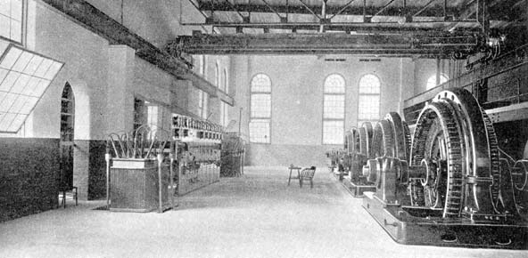
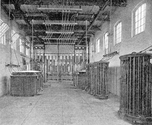
| Fig. 1. View of Interior of Greenville-Carolina Power Company's Station. |
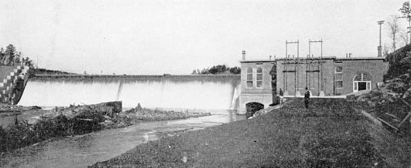
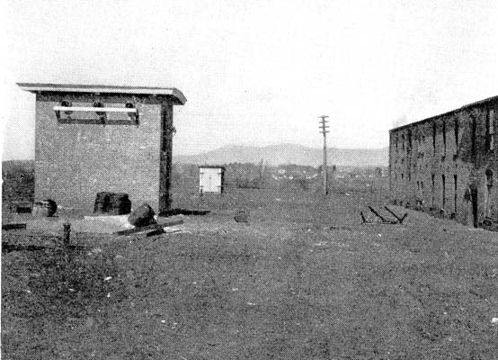
The location of the power house and dam is on the Saluda River at a point about five miles west of Greenville. This river rises in the mountains between North and South Carolina and has a fall above Greenville of six feet per mile. The drainage area is approximately 300 square miles. At the point selected for the location of the dam and power house, the river is about 100 ft. wide, having on the east or power house side, a bluff of ledge 100 ft. high, and on the west side, a gradually sloping hill.
Fig. 2 shows clearly the general arrangement of dam and power house. The dam proper is 275 ft. long, built on a curve of large radius, and is 47 ft. wide at the base and 9 ft. at the top. The up-stream side is vertical, the down-stream side being concave, with a long toe to turn the water. The headgate wall 130 ft. in length is a continuation of the dam and joins the solid rock on the east side. This wall forms the north wall of the power house. The abutment dam, headgate wall and foundation piers for power house were built on solid ledge and constructed of concrete with ballast stone interspersed.
POWER HOUSE.
The power house is of brick with concrete floor and tar and gravel roof. It is 84 ft. x 105 ft. with an alcove 14-1/2 ft x 40 ft. It is thoroughly modern in all details, well lighted, equipped for board carries the switch handles for operating the oil switches, ammeters, voltmeters and all low-tension apparatus.
The main exciter used in the regular operation of the station, has a capacity of 70 kilowatts, 125 volts, and is direct-connected to an independent wheel in order to obviate the trouble often experienced, of having the exciter affected by load conditions in the main generating system. There are three other exciters, two of 30 kilowatts and one of 12-1/2 kilowatts, all generating at 125 volts and all belted to the shafts of the main generators. The two 30-kw exciters are so arranged that they can be belted to either of the two 600-kw generators. The 12-1/2-kw exciter is belted to the 200-kw generator, thus forming a unit which is used alone to carry the night load, which load consists of the lighting of the town of Greenville and the running of motors. All wires from these exciters are carried in ducts imbedded in the concrete floor to the rear of the switchboard, and from the switchboard in the same character of ducts to the generators.
The load of this power house consists largely of cotton-mill load, and there is also a load in Greenville which consists of street railway, lighting and small motor load. The mill load, about 1500 hp, is a very steady load and is used from 6 a. m. until 7 p. m. The traction load is extremely variable and has a maximum of about 600 kilowatts continuing from 6 a. m. until 7 p. m. It will be noted that in the evening, the only load on the power house is a combination of the lighting and traction load, making a somewhat variable load, but one which is taken care of very satisfactorily by the apparatus in the power house. After midnight, the load is very light, consisting only of small lighting and power load in the city of Greenville. A Tirrall regulator is used in conjunction with the generators, in order to keep the voltage constant. All the apparatus for the power house was furnished and installed by the Westinghouse Electric and Manufacturing Company.
| |||
| Fig. 2. Exterior View of Greenville-Carolina Power Company's Plant. |
The operation of the station is in the hands of a superintendent and three assistants, who divide the shifts in such a way that there are two men in the station at all times. The night work is so arranged that each man has his portion, thus equalizing the hardships and giving every man experience in the station at all times.
On the hill to the east of. the power house, a comfortably furnished six-room cottage is provided with telephone connection, electric lamps and water works, this house affords a pleasant home for the men. These four men together with a lineman, who looks after trouble on the lines and building extensions of same, constitute the regular operating force.
TRANSMISSION LINES.
To insure the delivery of power by the transmission line, it was considered advisable to run two three-phase transmission lines on the same poles for the entire length of the line. It was therefore necessary in the various sub-stations, also in the power house, to provide switches by means of which the apparatus can be connected to either or both of the lines. All of the fixtures for this line are of heavy stock and were chosen with special care to getting good material. The standard size of pole is 35 ft. long with 8-in. top and is of Southern white cedar or juniper. The cross-arms are 3-3/4 in. by 5-1/2 in., of longleaf Southern pine and were creosoted after being placed in position. Each cross-arm is held firmly by means of two 5/8-in. bolts passing entirely through the pole, and by braces of angle iron thoroughly galvanized and fastened to the cross-arms and poles by means of galvanized lag screws. The pin was furnished by the Locke Insulator Manufacturing Company, and has a through bolt with oak top. The insulators were furnished by the Lima Insulator Company.
| |||
| Fig. 3. View of Pole Line. |
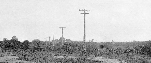
The standard spacing of the poles is 110 ft., but it was found is special places necessary to increase this spacing or decrease a profile and different lengths of poles used to avoid upward strain on the insulators. At angles in the line, poles carrying double cross arms were used, and where the angle was quite large, a group of poles was used with cross arms extending between them and transmission wires carried around the insulators, thus reducing the strain on the insulators to a small amount. In crossing telephone or telegraph wires, where it was possible to do so high poles and short spans were used, so that in case a wire should break in this span, it would not be long enough to hang down and touch the protected wire. At crossings where it was impossible to do this, a cradle was used which was made by carrying four steel cables between the poles and fastening across this at intervals of about four feet, pieces of 1/4-in. iron. With this method, it was considered that if the wire should fall, this cradle would catch it and hold it from coming in contact with the telephone wires. These cradles were permanently grounded by means of a copper plate buried in the ground near one of the poles. All of the wire used on this line is bare copper; that from the power house to the Brandon Mills, a distance of about three miles, is No. 2 and that from the Brandon Mills to the sub-station in Greenville is No. 3. The total length of the line is 5.8 miles.
SUB-STATIONS.
There are at present three main points at which power is transformed and delivered to customers or distributing circuits:
(a) The Brandon Mills, where approximately 1500 hp is used.
(b) The Carolina Mills, with a consumption of about 200 hp.
(c) The sub-station in the city of Greenville, with a capacity of 1155 kilowatts.
All of these buildings are of brick with concrete floor and tar and gravel roof, and in all provision is made for hoisting transformers out of cases to facilitate repairs.
| |||
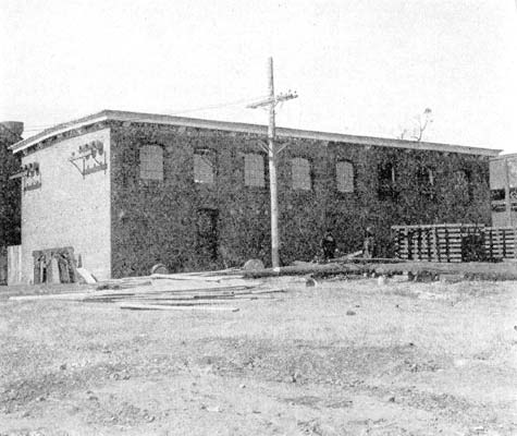
| Fig. 4. City Sub-Station From Which the Greenville Railway and Lighting Company is Supplied. |
The sub-station at Brandon Mills has three 500-kw oil-cooled transformers, reducing from 13,000 volts, three-phase, to 575 volts, three-phase, which voltage is carried to the mill and used in driving cotton mill machinery. The transformers are connected to the high-tension lines by means of fused circuit-breakers and double-throw link switches, which permit connecting the transformers to either or both of the lines. A three-phase oil insulated choke coil is interposed in the lines between the lightning arresters and transformers, for the protection of the latter. The low-tension wires, which are quite heavy, are carried from the transformers directly to the ceiling and then through the wall and over to the mill, a distance of about 100 ft. The measurement of energy is made in the low-tension wiring near the transformers, by means of a watt-hour meter. All of the apparatus for the station was furnished by the Westinghouse Electric & Manufacturing Company.
| |||
| Fig. 5. Interior View of City Sub-Station. |
The sub-station at Carolina Mills has three 100-kw transformers. These transformers are connected to the high-tension line by means of an oil switch. The secondary wires carrying 575 volts, three-phase, are in ducts beneath the concrete floor and run to the low-tension switch, from where they run to the ceiling and thence to the mill. This equipment of transformers, lighting arresters, switches, etc., was furnished by the General Electric Company, but installed by the Power Company.
| |||
| Fig. 6. Carolina Sub-Station. |
The sub-station in Greenville is of the same general type as the above, but is much larger, being 22 x 50 ft. in plan. It is located on a piece of property adjoining the power house of the Greenville Gas and Electric Light and Power Company, as this company uses the power for operating its railway system and lighting system, and its load forms a considerable and important part of the output of this sub-station. Both high-tension lines are brought in at one end of the buildings and after passing through independent three-phase oil insulated choke coils, are carried to the high-tension bus, which extends the width of the building. Immediately in front of the bus are the fused circuit breakers, and from them the wires are carried on the ceiling to the transformers located along the two sides of the building. The equipment for the railway service consists of three 135-kw transformers with a secondary voltage of 420. For furnishing the lighting circuit and small motors, the sub-station contains two 150-kw transformers supplying 2200 volts, two phase. The wires for both of these services are carried in multiduct conduit to the power house of the consumer, a distance of about 150 ft., the measurement of energy being made by watt-hour meters at the point where the wires enter the building. The cables which carry power for operating the railway, are connected to two 300-kw six-phase 60-cycle G. E. rotary converters and the same feeders supply an induction motor driving a direct-current arc machine. The 2200-volt circuit supplies directly the distributing mains for lighting and small power purposes in the city of Greenville:
This consumer uses the power exclusively in the operation of its systems and it has been found to be very satisfactory indeed, no accidents to machinery or other serious troubles having occurred to bring into question the reliability of the power. The demand of this service has been increasing continually, but the growth has been provided for by installing sufficient capacity in transformers and allowing space in the sub-station for the installation of additional transformers. Besides, the above, there are also located in the sub-station three 150-kw transformers supplying 2200 volts, three-phase, distributed by the Power Company to loads in the city such as machine shops, small mills, etc.
As is usually the case in a community where electricity is new and untried, it is being found that the sale of energy is very simple after operation of the system is begun, and even now negotiations are under way which will very materially increase the revenue of the company.
An item of importance in connection with this development is the fact that there is no ice whatever in the Saluda River at any time. The simplicity of this installation is very well illustrated by the fact that the entire pay roll of the company, outside of the president and treasurer, includes only six men.
The construction of the plant was carried out by the Federal Construction Company, of Boston, with Mr. A. G. Furman, vice-president of this company and president of the Greenville-Carolina Power Company and Mr. J. S. Viehe, electrical engineer. Messrs. Lockwood, Greene & Co., of Boston, were the engineers and furnished general supervision over the construction work.
