[Trade Journal]
Publication: Electrical World
New York, NY, United States
vol. 48, no. 2, p. 91-2, col. 1-2
100,000-Volt Experimental Transmission Line.
BY K. WERNICKE.
IN testing high-tension insulators for transmission lines, storm conditions such as rain, fog, snow, etc., are taken into account by pouring water over the insulator and determining the voltage at which the brush discharges, around the insulator to the pin, occur.
It would be far better and more in accordance with present-day practice to test insulators under actual operating conditions; that is, by mounting them on a pole in the open air and determining the voltage at which brush discharge occurs under various conditions of weather. Artificially produced rain can be taken as a substitute for rain which falls nearly vertically. However, as a matter of fact, rain is often accompanied by high wind and in many cases is driven horizontally against the insulators; in these cases artificial rain would be of little use in determining the behavior of the insulator under storm conditions.
Mr. Robert M. Frieze explains the cause of brush discharge over wet insulators, thus: The upper surface of the top petticoat of the insulator is rendered conducting by the film of rain water, and the little streams of water which fall from the edge of the top petticoat have the same potential as the line; therefore these streams do not follow the laws of gravitation, but are attracted toward the pin, which is of opposite potential; thus it is that the water forms a conducting path between the line conductor and the pin. A wind which drives the rain in a nearly horizontal direction will naturally assist the action described by Mr. Frieze, and thus lower the potential at which the discharge occurs to a value which truly corresponds to actual practice. Having once determined correct values for the potential of discharge it is possible to decide on a safe working voltage for the insulator.
Of course, it is not necessary, and in manufacturing on a large scale it is utterly impossible to test all insulators in this manner, since an incalculable amount of time would be lost in waiting for the desired weather conditions. A few samples of each type should be chosen and thoroughly studied and tested so as to make it possible to judge the quality of other insulators of the same type. Every insulator which leaves the factory should be subjected to the puncture test so as to detect faults in the material.
In order to test high-tension insulators under actual working conditions, the Insulatorwerke A. G. in Pankow, near Berlin, erected an experimental line equipped with insulators made by the Ambroin Werke (Kleinsteuber patent). It is thought that a description of this line should be of interest, since a pressure of 100,000 volts is used, and furthermore in addition to the transmission line in the open a part of the line is carried indoors and under conditions which could scarcely be called favorable. At two points in particular, special care was required, namely, where the conductors passed through a masonry wall and a doorway, respectively.
| |||
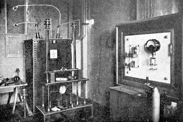
| Fig. 1. -- Transformer Room. |
The line commences in the transformer room (Fig. 1). In this room is located a 20-kw transformer built by the British Westinghouse Company and having a transformation ratio of 2:1000. In the foreground and at the right is the switchboard for the transformer. It is equipped, with a two-pole switch, an overload circuit breaker, a hot-wire voltmeter and a hot-wire ammeter, all in the primary circuit. Although the voltmeter is connected in the primary circuit, the scale is calculated, from the ratio of transformation, to read the secondary voltage. The ammeter is fastened at the side of the switchboard (not visible in the illustration). The primary current measured 18 amperes with the secondary on open circuit at 100,000 volts.
| |||
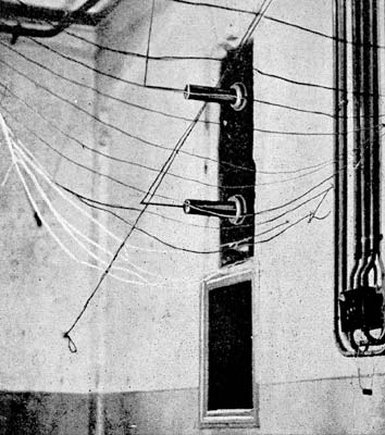
| Fig. 2. -- Wires Entering Transformer Room. |
In front of the switchboard is seen the regulator; this regulator is similar in construction to a railway motor controller and permits the variation of the pressure in steps of 10,000 volts. The sudden jumps from one voltage to the next higher, which were necessary evils with this style of regulator, often caused surges which would operate the breaker in the primary circuit. On account of these annoyances the above type of regulator was replaced by an induction regulator which permits a gradual change from the lowest to the highest voltage.
The line conductors, which consist of bare zinc plated copper wire 1.5 mm. in diameter, are carried through the wall above and at the left of the transformer (Fig. 1). The entry, which is shown in the illustration, consists of an Ambroin plate 1,000x1,000x25 mm. through which are passed two Ambroin tubes, 60 mm. outside diameter, 26 mm. inside diameter, 600 mm. long and 500 mm. between centers. Round metal rods are fastened in these tubes by means of Ambroin sleeves, the ends of the rods being provided with clamps for connection to the line conductors. Fig. 2 shows the entry from the other side. This illustration also shows the hemp string net which is strung underneath the line throughout its length in order to catch broken conductors and prevent them from reaching the ground. (The net was purposely made of non-metallic material to prevent condenser effect.)
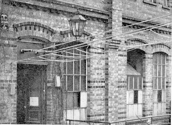
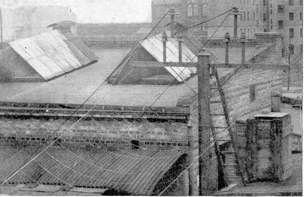
The conductors next pass through a narrow floor, and in order to do this they make a right angular turn. The wires are here carried upon Ambroin insulators supported upon wall brackets. Passing through the entry in the door the line reaches the open air. This entry is constructed in exactly the same manner as the one in the transformer room, except that the conductors are placed side by side instead of one above the other. Fig. 3 shows the entry from the outside. It may here be noted that the gas lamp which is very near the line, burned while the .experiments were being carried on and caused no trouble. (It is also worthy of note that the low-potential conductors laid in conduit, which can be seen in Fig. 2, near the entry, did not cause any disturbances worth mentioning.) The last stretch of the line passes over the factory court yard and ends on a wooden pole five meters high, upon which are mounted the insulators to be tested (Fig. 4). The insulators shown in the illustration do not belong to the so-called standard types, but were special forms which were used only in the first few tests.
| |||
| Fig. 3. -- Wires Entering Building. |
From Fig. 4 it is seen that the connections are so made that the insulator at the left is subjected to the full working line voltage, while the one at the right, in this case, serves only to insulate the incoming line. The four supports under the insulators, which are also made of Ambroin, serve to increase the insulation to the pole or ground or to insulate the insulator from the pole.
There is also an arrangement whereby a. considerable number of insulators can be set upon level ground and tested. For this purpose wires are led from the main line to the various points in the factory court yard where insulators are mounted to be tested under all sorts of weather conditions.
The first tests were limited to simple trials made to determine the safety and reliability of the installation. These consisted of impressing full voltage (100,000 volts) upon the line for one hour each day for three successive days. On the first day there was a heavy rain and on the two following days there were big snowstorms, nevertheless there were no noticeable disturbances, not even at the entries, which are the weakest points in the installation.
| |||
| Fig. 4. -- Arrangement of Insulators During Test. |
The only trouble experienced was caused by the opening of the circuit-breaker, when the voltage was raised too rapidly. Since, as was mentioned above, the voltage was varied in steps of 10,000 volts, an extra rise in current accompanied each advance of the voltage. Now when the operator did not pause about 15 seconds on each step the surges were so great as to cause the circuit breaker in the primary circuit to operate. When care was taken to pause at each step the disturbances were greatly reduced, but since the installation of the induction regulator there has been absolutely no sign of trouble from this source. The extra rise in potential could be detected along the line by a sharp clicking sound, so that the observer stationed in the factory court yard could follow the adjustment of the regulator from step to step without being in communication with the attendant in the transformer room. At 40,000 volts there is a perceptible corona about the wires and a humming sound which denotes the passage of electricity into the atmosphere. At 100,000 volts there is a corona at the points where the conductors pass through tubes in the entry plates; the transformer terminals and, in fact, everything connected to the line is surrounded by a glow of light. After the reliability of the installation had been proven, by the preliminary tests, the actual tests upon insulators were begun. The testing plant has now been in almost daily use for six months and works as well now as the first day it was put in service.
| |||
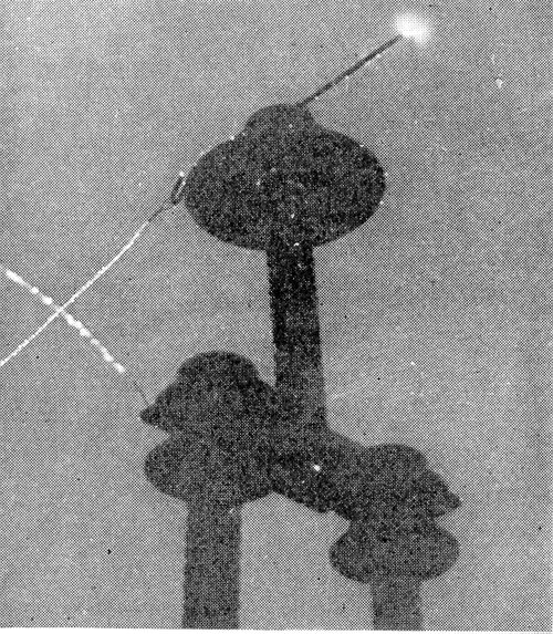
| Fig. 5. -- Formation of Corona at High Voltage. |
Fig. 5 shows one of the insulators mounted upon the wooden pole while being tested with 100,000 volts. The corona on the conductors is sharply outlined against the dark night sky and
·
·
[Missing text]
·
·

