[Trade Journal]
Publication: Electrical World
New York, NY, United States
vol. 67, no. 19, p. 1065, col. 1-3
Disk-Type Strain and
Pin-Supported Insulators
Disk strain insulators and pin-supported line insulators invented by Louis Steinberger of Brooklyn, N. Y., possessing a number of novel and important features, are shown in the accompanying illustrations.
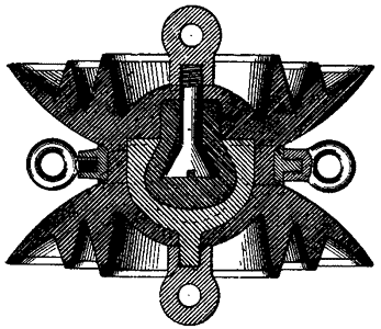
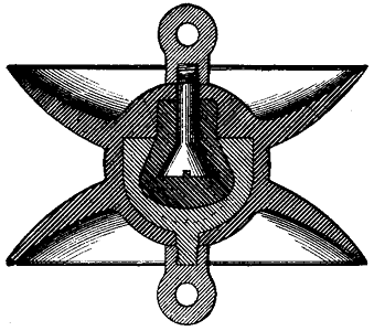
The strain insulator is provided with a plurality of disk members integral with the body portion, as shown in the sectional view in Fig. 1. The outwardly extending members of annular form are made integral with and formed on one side of each of the disks, as shown in the illustration, for the purpose of providing a large amount of surface to take care of possible leakage of current. Disk strain insulators are also made with a plurality of plain disks formed integrally with the body portion, as shown in Fig. 2. Basket and bolt types of metallic strain members are embedded within the body portion, but insulated from each other by a fireproof material, as shown. The eyes or terminals of the strain members are detachable, and terminals of other forms, and for other and special uses, such as devises, sockets, threaded studs, etc., may be employed when desired or required.
 |
| Fig. 1 — Strain Insulator Having Disks With Outwardly Extending Members. |
When these insulators are employed for supporting arc lamps, etc., a metal ring is molded or placed around the body portion intermediate of the two disks, as shown in the illustration. The device may then receive mechanical stresses in four directions.
The metal annular rings engaging the peripheral edges of the disks, and the outwardly extending annular members, as well as the metal ring encircling the body portion of the insulator, and as shown on the pin-type insulator, also on the disks or hoods, possess noteworthy features, namely, equalizing the dielectric stresses, and providing a path for arcs, allowing a harmless dissipation of their energy. They also provide means for the redistribution of the electrostatic field surrounding the insulator, by placing some capacity on its surface. They also practically prevent the puncturing of the insulator by abnormal electrical potential discharges without reducing the effective insulation of the line.
 |
| Fig. 2 — Strain Insulator With Plain Disks. |
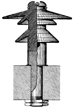
The pin insulator shown in Fig. 3 possesses all of the electrical and mechanical advantages possessed by the disk strain insulator, and in addition it is also practically a lightning-proof insulator, because of the fact that the supporting pin is attached to the insulator instead of penetrating it, as in the ordinary types of pin insulators. The body portion being made up of a solid integral mass of insulating material provides very high resistance, and affords no chance for the lightning to puncture it, as the path around the outside of the insulator is of much lower resistance, and the current would naturally follow that path.
 |
| Fig. 3 — Pin Insulator With Pin Attached to It Instead of Penetrating It. |
The body of the pin insulator shown in Fig. 3 is provided with a plurality of protective annular flanges or disks, the object of which is to maintain certain portions of the insulator dry when moisture is present, and to lengthen the surface distance between the ends of the body portion of the insulator. The outer annular edge of each flange is provided with a ring of conducting material; upon the upper surfaces of the flanges are embedded other conducting rings. These various conducting rings are arranged so as to dissipate as quickly as possible any charge which may tend to travel from the conductors in the upper grooves downward. The rings are so placed as practically to compel the passage of the charge over the surface of the flanges rather than through the material of the flanges or the body portion, so that while some of the rings are relatively close together, they are separated by walls of insulation around which the charge is practically compelled to pass in going from one ring to another. The principle involved in the design of this insulator might be described as embodying a conductor extending from the line to the ground, and comprising alternate annular sections of high and low resistance, the sections of low resistance tending to distribute the charge, when abnormal, and thus to protect the conductor from injury and the sections of high resistance affording ample impedance to the passage of normal charges.
