[Trade Journal]
Publication: American Electrician
New York, NY, United States
vol. 10, no. 10, p. 447-450, col. 1-3
THE TRANSMISSION PLANT OF THE FRIES MANUFACTURING
& POWER COMPANY.
In the State of North Carolina there are a great many undeveloped water powers varying from 1000 to 10,000 h.p. in capacity, and among these has been selected for development one which is known as the "Shoals," and which is located on the Yadkin River, at a point about 14 miles by road from the twin cities, Winston and Salem.
The fall at this point is about 8 ft., and took the form of rapids before its development. In previous years a portion of this power has been used to operate a saw and grain mill.
The development of this power was by no means a simple problem, for the river, rising as it does in the foothills of the Blue Ridge range, is subject to severe freshets in the rainy season. The country above the power house site is low lying and the employment of a high dam would create considerable land damage. Even so slight an increase of head as 2 or 3 ft. was not practical, and hence the dam could effect but little storage of hydraulic power, and the somewhat irregular flow of the river had to be in a measure depended upon. This is estimated to give with a 10-ft. head from 2000 to 2700-h.p., with a yearly average of about 2300-h.p.
 |
| Fig. 1. General View of Power House and Dam. |
To develop and transmit this power to Winston-Salem the Fries Manufacturing & Power Company was organized.
The plan decided upon by the company's engineer was to build a 10-ft. dam across the river at the "Shoals" and install in a suitable power house a sufficient number of turbines to generate 1000 h.p., the remainder of the available power to be taken care of by future addition.
It was decided to directly connect electric generators to the turbines and to transmit the energy in the form of three-phase currents at a pressure of 10,000 volts to a sub-station in Salem. From this station within a mile radius power is to be distributed at 1200 volts, and for greater distances the power-house pressure will be used. Of course, it is to be understood that at the places where the power is actually used, it is reduced to the proper voltage by suitable step-down transformers.
For the motor service induction types are used when the units do not exceed 50 h.p and in larger sizes recourse is had to synchronous motors. The electric system adopted was the well-known S. K. C. system, the apparatus for which is built by the Stanley Electric Manufacturing Company of Pittsfield, Mass., and it is to be used throughout.
| |||
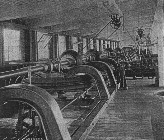
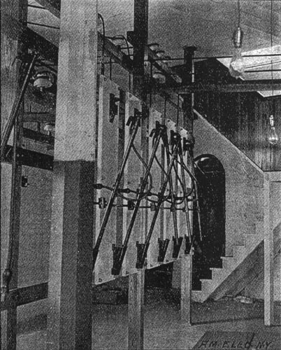
| Fig. 2. View of Main Shaft and Governors. |
The hydraulic work was begun in May, 1897, and great precautions were taken to avoid damage from floods and freshets. The dam, of which the frontispiece is an excellent illustration, is built of rough stone, and is 500 ft. long and 10 ft. from the sill to the top of the spillway. At the ends the height is raised by steps to a maximum of 13 ft. The width of the dam is 6 ft. on the top, increasing to double that amount at its base. For a space of 6 ft. in the length of the dam the head is reduced to 9 1/2 ft., where the fish ladder is placed.
The power house is built of brick and surmounts the wheel pits, which are of rough stone. It consists of a generator room and a wheel room, at right angles to each other. The wheel room extends for its entire length into the river, its foundation meeting the dam. It is 145 ft. x 36 ft., and is divided into eight wheel pits or open penstocks, the lower side of each being arched and opening into the tail race. The division walls of the wheel pits are of brick, and also serve as a foundation for the frames carrying the shaft and bevel gears. Each wheel pit is to be equipped with two turbines, with a 2 ft. x 12 ft. waste gate between them.
The present installation consists of one turbine in each pit. They are of the McCormick vertical gear type, manufactured by the S. Morgan Smith Company, of York, Pa., and deliver 165 h.p. each when running under a head. of 9 ft. The wheels are submerged and are mounted on a 6-in. pine flooring, supported on I-beams 8 ft. below head water. The draft tubes pass through the floor and extend to the tail race 2 ft. below. Fig. 6 illustrates one of these turbines as it appeared before installation.
The eight wheels are geared onto a horizontal shaft, mounted in bearings supported by the division walls. The vertical turbine shafts carry a large bevel gear with hard wood teeth, meshing with an iron bevel pinion keyed to the horizontal dynamo shaft. Fig. 2 shows this arrangement to good advantage.
The dynamo shaft is in two sections, each driven by four wheels, and by means of a coupling four or eight wheels may be used. The system is governed by two Lombard type B governors, one tor each set of wheels. The governor controls only three in a set, the fourth being controlled by hand.
| |||
| Fig. 3. Generator and Switchboard. |
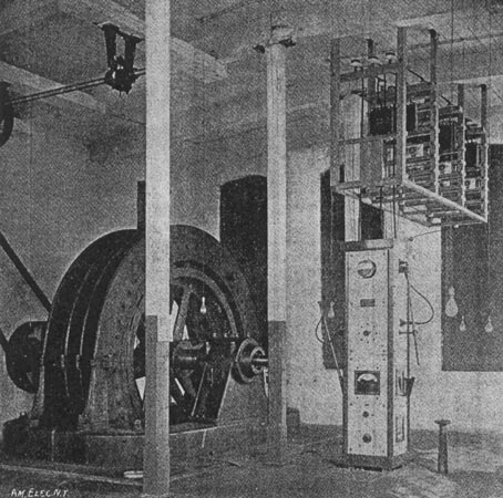
The generator room is but one story high and 39 by 60 ft. in floor dimensions. It is surmounted by a frame roof 18 ft. from the floor and supported by posts. There is ample room for two generators, with their necessary accessories, but at present there is but one machine with its exciter and switchboard installed. This machine is of the S. K. C. three-phase inductor type and has an output of 750 k.w. at 166 r.p.m. It is particularly interesting, as it is wound for 12,000 volts, and delivers three-phase currents at this pressure to the line without the use of step-up transformers. The efficiency of this machine at full load is claimed to be 93.5 per cent, and its exciting current is but a trifle over one-half of one per cent of its output, being about 86 amperes at 45 volts. The rise in temperature of the hottest part of this machine is but 28 degs. F.
This machine is mounted on a pit foundation, extending 25 to 30 ft. to bed rock, and the pit is thoroughly grouted and plastered within to keep out any high water.
The generator frame is 10 ft. 1 in. in diameter and is divided vertically in such a way that the two halves can be separated on the shaft, allowing room on the inside of the armature for repairs. These are of the simplest character, consisting merely of the renewal of a stationary coil or so, which are readily slipped into place.
The exciter is a 14-k.w. four-cole Crocker-Wheeler machine, driven at a speed of 1100 r.p.m. from the water wheel shaft. It can deliver its current at 70 volts, and is large enough to excite the fields of two such generators. It is interesting to note that the regulation of the water wheels is so close that no separate exciter turbine was needed.
| |||
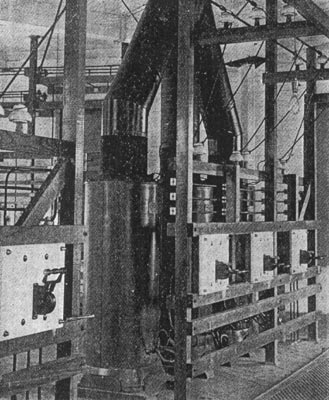
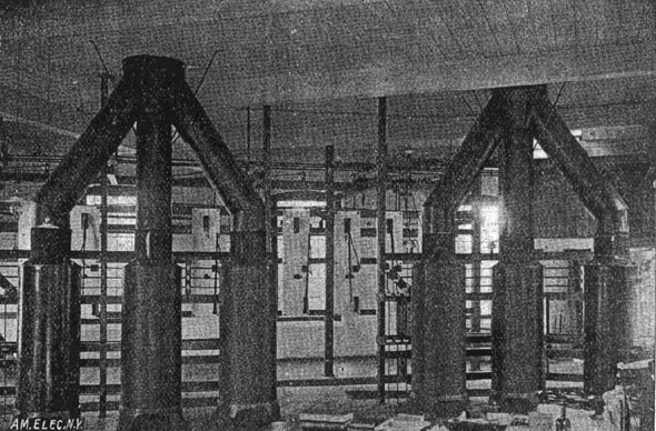
| Fig. 4. Switches and Power Transformers at Sub-Station. |
| |||
| Fig. 5. Collecting Board. |
The switchboard consists of four white marble slabs formed into a pillar 21 ins. square by 9 1/2 ft. high. The mountings are of lacquered brass and are trimmed in oiled hard wood. This construction is very neat and compact, and as all live contacts are concealed within the pillar it is perfectly safe. Upon the board are mounted three high-tension single-pole single-throw switches. They are of the plug type, with long handles and a bayonet lock. Two 12,000-volt static ground detectors are also used and are connected in such a way that the needles deflect toward the grounded wire.
 |
| Fig. 6. Type of Turbine Used. |
The generator voltage is read from a static voltmeter connected to the secondaries of a transformer stepping down to 2000 volts. The board is also provided with an alternate current ammeter, a voltmeter and a switch for the exciter circuit, and the exciter shunt rheostat. The field rheostat, the hand wheel of which may be seen to the right of the board, is suspended from the floor 18 ins. below, to .provide ventilation and economize space.
| |||
| Fig. 7. Power Transformers. |
Above the switchboard and extending to the wall is seen a lightning protection rack, which comprises three vertical sections, each of which carries a set of arresters and choke coils for each leg of the high-tension circuit. These protection sets, like those used at the other points of the line, have choke coils in series with each leg of the circuit, with S. K. C. arresters connected in such a wry that there are always four arresters between the line and ground.
The station wiring is placed under the floor. The high-tension wires are insulated for 25,000 volts, and in addition are supported by triple petticoated porcelain insulators on horizontal cross arms. They reach the switchboard by passing through the floor at the base of the pillar. The three power wires pass out of the tops of the pillar and connect to the line.
The line is 70,000 ft. in length and extends from the power house to the sub-station in Salem. It consists of three No. 1 soft-drawn copper wires strung on 6-in. triple petticoat porcelain insulators supported on two cross arms. The three wires are 24 ins. apart and form an equilateral triangle, of which the lower cross arm is the base. There are two transpositions in the line, thus giving the triangle two-thirds of a rotation. The line follows the railroad almost all the way to Salem, and the wires are placed on the sides of the pole away from the track to facilitate the stringing of a duplicate set.
The poles are of white cedar and from 36 ft. to 48 ft. long. They are set from 5 1/2 ft. to 6 ft. in the ground and spaced 100 ft. apart, excepting where the line crosses a highway, where they are set 50 ft. apart. Each pole carries three cross arms, the lower two being used for the power circuit. The top arm has six pins. Of these the outer pins carry a barbed wire ground circuit and the inner, pins a telephone circuit, which can also be grounded in case of storm. The extra pins are used in transposing the telephone circuit, which is done every 500 ft. At every mile in the length of the line a branch from the telephone circuit is taken down the pole to within a short distance of the ground, so that frequently communications can be had with either end of the line. The barbed wire is grounded every 1000 ft. through a 54-in. galvanized iron pipe driven 10 ft. into the ground at the base of the pole. The poles are all numbered and the line construction is otherwise very complete.
 |
| Fig. 8. 300-H. P. Synchronous Motor in Arista Cotton Mill. Fig. 9. 80-H. P. Synchronous Motor in Woolen Mill. Fig. 10. 300-H. P. Synchronous Motor at South Side Mill. |
The line enters the sub-station on the second floor and is duly provided with lightning protection, from whence it passes to the main bus bars on the first floor. From these bars three three-pole high-tension circuits are taken through nine single-pole high-tension plug switches. The first of these circuits connects to another set of bus bars, to which the power transformers shown in Fig. 7 are connected three-phase, two sets in parallel. The second high-tension circuit passes through a lightning protection rack and passes to what is known as the fertilizer line. This line is 3 1/2 miles long, and consists of three No. 6 insulated wires, and terminates in a fertilizer works, at which the pressure is reduced by three 25-k.w. oil transformers, to 600 volts, and at that pressure supplies two induction motors, one of 50 h.p. and the other of 30 h.p.
The third high-tension circuit passes through lightning protection and connects with what is called the South Side line. The line is 2 1/2 miles in length, and, like the fertilizing line, consists of three No. 6 insulated wires. It passes at what is known as the South Side mill to three 75-k.w. power transformers, which step down to 600 volts and supply current to a 300-h.p. synchronous motor, shown in Fig. 10, a 10- h.p. induction motor, and three 80-light transformers. The general construction of the second and third high-tension circuits is similar to that of the main line, with the exception of the telephone circuits. It may also be added that the poles are higher, to avoid the city wires.
The primary board in the sub-station is placed about 8 ft. in front of the west wall and parallel therewith. It consists of nine long-handled high-tension switches, having marble bases and mounted on a wooden framework. In the middle leg of the high-tension circuits is placed a Thomson ammeter, mounted on a marble slab.
The collecting board, shown in Fig. 5, is a wooden framework, on which are mounted six double-throw single-pole self-inclosing slide switches. These switches connect the secondaries of the transformers through twelve single-pole porcelain fuse blocks to the 1200-volt bus bars extending to the distributing board. The distributing board shown in Fig. 6 also has a wooden framework, upon which is mounted six 350-ampere single-pole throw switches on marble bases, two Thomson ammeters, two static ground detectors and one Bristol recording voltmeter. From this board two 1200-volt circuits are taken. One supplies current to a 300-h.p. synchronous motor and to two 80-h.p. motors of the same type in the Arista cotton, grain and woolen mills. These are shown in Figs. 8 and 9.
The second circuit supplies current to one 300-h.p. synchronous motor in the Wiston-Salem Electric Station, and to two induction motors of 50 h.p. and 30 h.p. in other shops.
The transformers are of the vertical self-ventilating type. They are ventilated as shown by large iron pipes extending through the roof to a hood about 3 ft. above. The working temperature is however very low and the commercial efficiency is not impaired.
The ground detectors in use throughout are of the static type. The ground wires for the several sets of lightning protectors are of No. 1 copper wire, securely soldered to large copper plates set from 6 ft. to 10 ft. below ground and imbedded in powdered charcoal. The plates are either in naturally wet places or are kept damp by periodically pouring water into a pipe connecting with them.
A duplicate or larger unit and line will shortly be added, as the capacity of the present generator is nearly reached.
