[Trade Journal]
Publication: Street Railway Journal
New York, NY, United States
vol. 30, no. 12, p. 412-416, col. 1-2
MIDDLETOWN-BERLIN ELECTRIFICATION OF THE NEW
YORK, NEW HAVEN & HARTFORD RAILROAD
COMPANY
The New York, New Haven & Hartford Railroad Company, realizing the importance of electric traction as a feeder for its main lines and also as a factor in building up the smaller towns, has converted several of its branch lines from steam to electric operation. The most recent of these are the two lines running from Middletown, Conn., to Berlin, Conn., and from Middletown, Conn., to Meriden, Conn. just completed by Latey & Slater, engineers, of New York City, under the direction of E. H. McHenry, vice-president of the New Haven company.
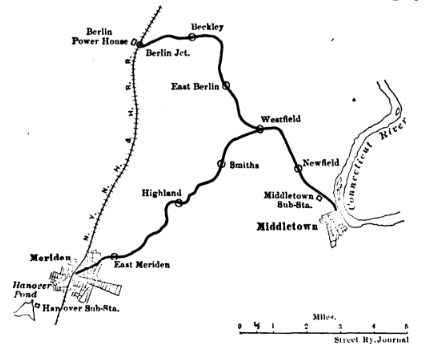 |
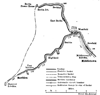
| Map Showing Lines Equipped |
The Middletown-Berlin branch, 9.53 miles in length, connects Middletown with Berlin Junction on the Hartford division of the main line between New York and Boston, and the Middletown-Meriden line branches from the former at Westfield, Conn., and connects Middletown with Meriden, also on the Hartford division, 7.21 miles from Westfield, as shown in the map. These roads are to be utilized as part of the system of the Consolidated Railway Company, the power to operate them being obtained from its power and sub-stations. Connections will also be made at each terminal with the local street car line.
 |
| Diagram of Transmission Circuits |
In pushing this work, which was done during the winter months, a much greater use was made of a work train as a factor in the construction work than is usually done.
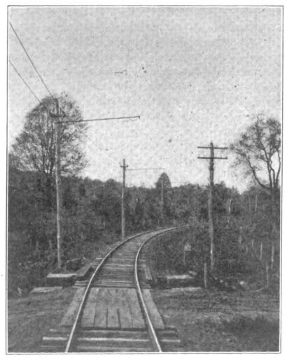
A bracket construction for the trolley wire is used on the tangents and on all curves where the tension of the trolley and feed wires is against the rake of the poles, 12 ft. 6 in. brackets being used on the tangents and 14 ft. brackets on the curves. All other curves, double track and turnouts are of span construction. The poles are of chest-nut, having tops 8 ins. in diameter and are spaced approximately 110 ft. apart, with the face of the pole at top of rail 10 ft. from the center line of the track.
| |||
| Curve Construction |
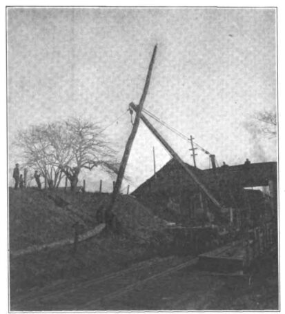
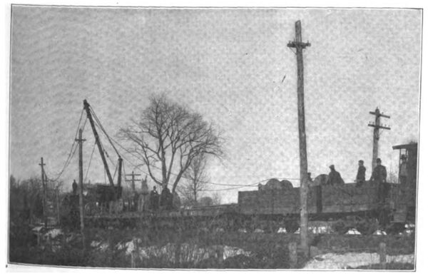
The poles were distributed by train and after being framed, graded and armed on the ground were erected in place by the use of a steam derrick mounted on a flat car as illustrated. This method of setting poles proved quite a satisfactory orfe and on a line where the work would not be interrupted by trains would be extremely economical, because under the operating conditions on these lines with frequent train interruptions it was possible with twelve men to set and tamp forty-six 35-ft. poles in a nine-hour day.
| |||
| Small Tower Car |
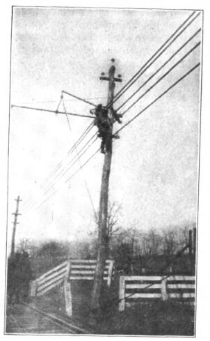
In order not to interfere with the trains and to obviate the dangers incident to the use of ladders in the erection of brackets, a novel and very economical device was used. This consisted in an arm having a wire head guy on one end the noose of which slipped over the top of the pole, and a curve yoke on its other end which fitted around the pole. At the outer end of this arm was fastened a single block and fall by means of which a man on the ground could hoist the brackets into place for two men up the poles to fasten and adjust them. With this rig it was possible for two men on the poles and one man on the ground to erect and adjust thirty-six brackets in one nine-hour day.
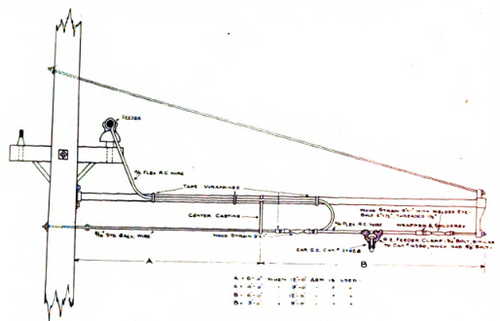 |
| Overhead Bracket |
The poles are very generously guyed both head and back, 21-inch wood strain insulators being used on the guys on all poles carrying the transmission line, and 9½-inch wood strains on all other poles. The anchors consist of 3/4 in. x 6 ft. galvanized iron eye rods run through one-half of a 5 in. x 8 in. x 8 ft. tie, as a dead man buried 5 ft. under-ground. The cross-arms are of two lengths for two and four insulators, and all poles on curves are double-armed for both feeder and transmission.
| |||
| Erecting Brackets |
The trolley wire is No. 0000 hard drawn, grooved copper wire, and is erected 22 ft. above the top of rail. The trolley wire is anchored by means of anchor ears and strain plates in two ways; on bracket construction, head guys are run to the tops of the poles adjacent to the anchor strain plate and the anchor pole is held in alignment by means of a brace pole. On the span construction the strain plates are guyed to the two adjacent poles on each side of the anchor span.
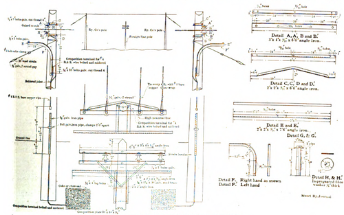 |
| High Potential Line Construction for Crossings |
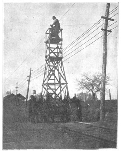
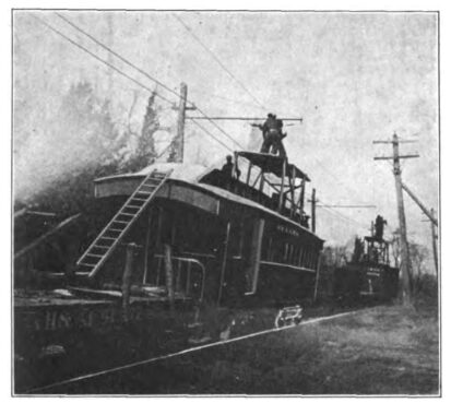
The work of stringing and building the trolley wire in place and obtaining its proper alignment was very greatly expedited by means of two kinds of tower construction. On the portions of the tracks with the least traffic, two box cars were fitted up with collapsible platforms. These were drawn by a locomotive and by having two flat cars placed between them they were spaced so that two poles could be worked upon at a time. On the portions of the roads where the traffic was heaviest a light skeleton tower with a collapsable [sic] collapsible top was mounted on four wheels. This was of such weight that four men could lift it clear of the track very easily, so that by the use of flagmen both before and behind it was possible to use this tower to the greatest advantage. All the trolley wire was strung with the locomotive and tower cars, the clipping in and building of curves being done by the smaller tower.
| |||
| Tower Car Train |
At all switches in the trolley wire the end of the switch trolley wire is guyed through a 9½-inch wood strain insulator to the next pole ahead, so that the switches are under no strain from the trolley wire.
On all curves of 2000 ft. radius or under a bridle construction is used with pull-offs, varying in number with the degree of curvature.
The power to operate these lines is obtained from the Berlin power station in the shape of three-phase alternating current at 11,000 volts, in which form it is transmitted aerially to the sub-stations at Middletown and Meriden.
| |||
| Setting Poles by Construction Train |
At these sub-stations it is transformed and converted into 600-volt direct current, in which shape it is delivered to the trolley wire. There is also a rotary converter in the Berlin power station, so that the line is really supplied from its three termini.
The transmission line from Berlin to Middletown is carried on the trolley poles along the right of way and the line to Meriden is carried on poles along the right of way of the Hart-ford division.
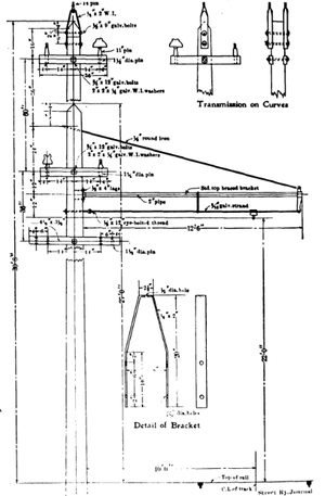 |
| Trolley Construction With and Without Transmission Line |
The three conductors, each of No. 4 B & S gage, semi-hard drawn solid copper wire, are supported on and tie to double petticoat porcelain insulators. There are three transpositions of the conductors, making one complete revolution between terminal points. At all transposition points two poles with the standard cross arm construction are placed 25 feet apart and thoroughly head guyed. The conductors are each rotated through an angle of 120 degrees between these poles, are drawn tight and thoroughly tied, so that there will be no sag in them at these points, due to expansion and contraction.
| |||
| Stringing Feeders |
At all points where the transmission line crosses foreign wires and steam railways a special construction was used. The poles on each side of the crossing are securely head guyed and equipped with angle iron crossarms between which are held, on iron pins, porcelaine [sic] porcelain high tension insulators. Five-sixteenth-inch galvanized iron steel span wires are drawn tight between these insulators and the transmission conductors are brought from the triangular position to a horizontal plane and tied to the span wires at 61ft. intervals. This makes a very safe construction because both span and transmission wires must break before either can fall to the roadway and only the former is under any particular strain. To provide for the possibility of breakage of these wires, galvanized iron arms are carried below the transmission wires, so that if they slacken they will come in contact with the arms. These arms as well as the arm supporting the strain insulators are grounded through a piece of No. 4 wire attached to them and carried down the pole to a copper plate buried in charcoal in moist earth.
| |||
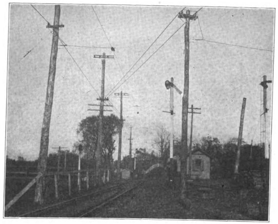
| View of Completed Track |
The direct current feeders are carried on the trolley poles on both branches and are of weatherproof stranded wire of various sizes. The positive direct current feeders are tapped into the trolley approximately every 1000 ft. Lightning arresters are cut into the positive feeder taps approximately every 2000 ft., the ground being made by means of a coil of trolley wire buried in charcoal in moist earth.
The negative direct current feeders are tapped into the track rails approximately every 1200 ft. Both the transmission and direct current feed wires were dropped in place on their cross arms by means of the derrick used for erecting poles, and pulled up to their desired tension by means of the train. This is about the simplest way in which wires can be handled, and that it is very economical can be judged from the fact that it was possible to string and pull up three lengths of 500,000 circ. mils, about 2600ft. each, of weatherproof cable, two lengths on one side of the pole and one on the other, in 84 minutes, with seven men besides the train crew. If the hoisting engine on the derrick had been equipped with a double drum and the derrick boom with revolving hopp, four of these men could be dispensed with.
The track is double bonded at each joint of each rail with No. 0000 stranded cable bonds around the fish plates, painted to prevent corrosion and make them less conspicuous. These bonds are of the solid compressed terminal type, compressed into holes drilled in the rail, by means of 35-ton, double-screw compressors.

