[Trade Journal]
Publication: Cassier's Magazine
New York, NY, United States
vol. 15, no. 5, p. 331-358, col. 1-2
THE ROME-TIVOLI ELECTRIC INSTALLATION
By Alfred O. Dubsky
THE first electrical plant which was put in operation in Rome, in 1886, would to-day be considered a very modern one, for it had only two units of 150 horse-power each. These machines, however, were the largest alternators constructed up to that time, and the plant was the first demonstration of a high-potential distribution of electricity to a large net for a city supply with underground concentric cables and house-transformers for private consumers and street illumination. With this as a beginning were evolved the present electrical works, which have a total output of about 5000 H.P., and comprise a variety of interesting engineering features.
It should be noted at the outset, that the present electrical works of Rome consist really of two generating stations. The older, a stem plant, has a total capacity of 2700 H.P., and was built in the city of Rome itself, in the Cerchi quarter, on the site of the ancient Circus Maximus. The newer hydraulic plant was erected at Tivoli about 27 kilometres 17 miles from Rome. The current generated in both stations is consumed in Rome for input candescent and arc lighting for driving electric motors used by private consumers and for the operation of the electric tramways.
The 2700 HP steam plant of Cerchi produces an alternating current of 2000 volts which is distributed by four underground cables to the transformer stations. Step down transformers, assembled in a number of secondary stations, provide the low tension circuits with current. The other plant at Tivoli generates alternating current at a tension of 5500 volts and the dynamos of this station, as already intimated, are driven by turbine-wheel. The electric power is conducted from there over a line of 27 kilometres to a large transformer station at the Porta Pia, one of the gates of Rome where the voltage is reduced according to the several uses of the current for private consumers, municipal street arcs and for the tramway supply.
The current coming from Tivoli is, therefore divided to three distinct trans
·
·
·
·
·
·
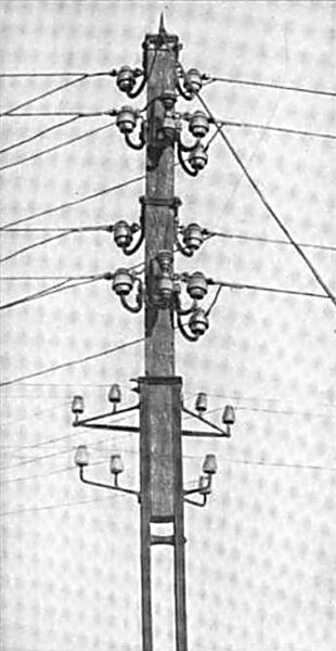
| |||
| Fig 14 -- the Pole at Half-Way Station. |
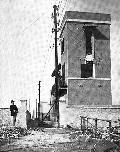
| |||
| Fig 15 -- the Half-Way Station Between Tivoli and Rome. |
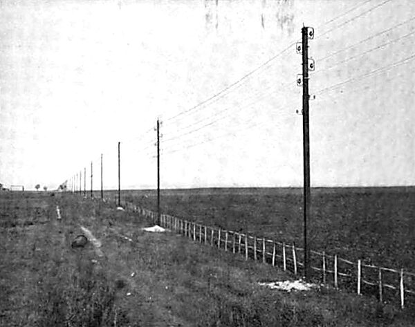
| |||
| Fig 16 -- the Transmission Line. |
 |
| Fig 17 -- Cross Section of One of the Insulators. |
All the insulators used were designed by Prof. Mengarini, and were furnished by the Ginori Works, at Florence. One of the high-tension insulators is shown in section in Fig. 17. It has two rims, the interior one dipping into a porcelain vessel which is filled with mineral oil. The oil does not appreciably increase the insulation of the line, but simply keeps it constant by preventing insects from building their nests in the interior of the insulator. This precaution was demanded by the special climatic circumstances of the Campagna Romana, and proved to be efficient during the period of a little over five years that the Tivoli-Rome line has been continuously in service, -- a comparatively long time in the short history of the electric high-tension power distributions.
The insulator support ends in a form of stirrup-iron, clamp around the wooden top of the pole. The frame visible in Fig. 16, which incloses each insulator, is made of strong iron wire. It prevents the line wire from falling down if either of the connections should break or become detached from its support.
Each pole is covered with lead on its top and carries a bundle of copper points which communicate with the iron structure forming the pole proper. This serves as a lightning conductor.
As mentioned above, the telephone and telegraph lines are fixed directly to the iron part of the pole. Phosphor bronze wire is used for both the main and return circuits. In order to avoid the influence of induction, which, as alternating currents are used, would be disastrous to the telephone service, the wires are alternated at every tenth pole, or, thus, every 1500 feet. The absolute potential of the telephone line with regard the earth (or the pole) gets a very sensible and disagreeable shock. In this way the telephone and telegraph wires, located under the four high-tension wires, for an effective guard against coming in contact with the dangerous high-tension conduit.
There are four small stations along the line which are provided with a telephone, so that the line guard is able to readily communicate with the terminal stations.
The extreme height of a pole when erected is about 31 feet, and the lowest high-tension wire is a little over 24 feet above the ground. The wires themselves are 4 feet apart, vertically. The distance between two poles is 150 feet, except when the line crosses the River Anio or the railway tracks. At those points the distance is somewhat greater. Altogether, 707 poles are used.
The sectional area of the conducting copper cable is 0.161 square inch, and it consists of 19 wires, each of 102 mils diameter. A long series of careful tests were made with the copper to be used before deciding upon its availability. Finally the order was given to the Metallurgic Society, of Livorno.
The insulators are cleaned every two years, and then the mineral oil also is renewed, and at the same time the poles are newly painted. Fig. 16 will give a very good idea of the general character of the power line.
·
·
·
·
·
·
[not finished]