[Trade Journal]
Publication: Engineering News
New York, NY, United States
vol. 35, no. 2, p. 27, col. 3,1-3
THE PASSAIC & NEWARK ELECTRIC RAILWAY.
(With Inset).
An electric railway from Passaic, N. J., to a connection with the lines of the Consolidated Traction Co., of Newark, is now being built by the Passaic & Newark Electric Traction Co. The total length will be 6.13 miles, of which 4.05 miles, from Passaic to Franklin, have been completed and are in operation; another length of 1.23 miles from Franklin south to the Belleville township line, has just been completed and will soon be in operation, and the remaining length of 0.85 mile will be proceeded with as soon as the franchise has been secured from the township of Belleville. The contractor is Mr. L. W. Serrell, of 99 Cedar St., New York. The engineers are Messrs. Wise & Watson, of Passaic, N. J., and we are indebted to Mr Colin R. Wise for drawings and general information. Gen. Bird W. Spencer is President of the company.
The contract includes furnishing all tools, materials and labor, grading the roadbed, laying and surfacing the track, laying 5 ins. of macadam (and 12 ins. on Washington Ave.), extending existing culverts and constructing the overhead wiring, etc.
The rails, Fig. 1, are of steel, of girder section, with side-bearing heads, and weigh 70 and 85 Ibs. per yd., the heavier rails being laid on Washington Ave. They are laid with broken, suspended joints, spliced with 24-in. flat plates and six bolts, spaced 4, 4-1/2, 4-1/2, 4-1/2 and 4 ins. c. to c., as shown in Fig. 2. They are secured by spikes 9-16 x 5-1/2 ins. to cross ties of white, post or burr oak or chestnut, the ties being 6 x 7 ins. section and 7 ft. long, spaced 25 ins. c to c., or 14 ties to each 30-ft. rail. Combination braces and tie plates of 7/16-in. steel are used, four to each rail on tangents and six on curves. These plates, shown in Fig. 1, have a base of 10 x 4 ins., and weigh 4 Ibs. each. The gage is 4 ft. 8-1/2 ins., widened on curves, and the super-elevation on curves is given by raising the outer rail or lowering the inner rail as occasion demands. All rails requiring to be cut must be sawed, no cutting by cold chisels being permitted. The tracks are 4 ft 8-1/2 ins. apart between gage lines of inner rails, except on Washington Ave., (which is 100 ft. wide), where they are laid at the sides of the telford paving, or 22 ft. 6 ins. apart, as shown in Fig. 3. Split switches and rigid frogs are used.
All the rails have two 9-16-in. holes at each end for two Chicago rail bonds of No. 00 B. & 8S. gage tinned copper wire, Fig. 4. These bonds are placed so deep that no wheels can reach them and shear them off. Cross bonds are placed at intervals of 200 ft., and connected to the rail bonds on either side by two tinned copper wires. On double track there are cross bonds at intervals of 1,000 ft., these being the same size as the rail bonds. The bonding is shown in Fig. 5.
The poles are of wood and iron, the latter being required by the county authorities on Washington Ave. The wooden poles are of long-leaf yellow pine, 30 ft. long and octagonal in section. The bottom is treated with a preparation of coal tar, or seine equally good preservative, to a height of 6 ft., and the remainder is given two coats of olive green paint. The poles used on tangents are 10 ins. diameter at the butt and 8 ins. at the top; while these used at street corners, or which in any way bear much of the pull of the trolley or feed wires, are 13 and 10 ins. diameter at the butt and top respectively. All poles on tangents and on curves of 300 ft. or greater radius, are set 6 ft. in the ground, and have a rake of 4% (or 0.96-in. in 24 ft.). Those at corners and terminals, and others which have to bear a heavy strain, are set 6 ft. 6 ins. in the ground (set in concrete), and have a suitable rake. The poles are not more than 125-ft. apart, and are placed 12 ins. inside the curb line of the street. Corner poles are fitted with strong eye-bolts for the attachment of guy wires, etc. No pike poles were allowed to be used in the erection of the poles, nor spurs used in painting them. The cross-arms are of the best pine, 3-3/4 x 4-1/4 ins., and are snugly fitted in gains in the poles, and each secured by two iron braces 1/4 x 5/8 x 28 ins. At all corners the poles are fitted with double cross-arms. The insulator pins are of iron at the corners, and of selected oak or chestnut on straight line work. They fit the cross-arms closely. The poles and cross-arms are shown in Fig. 6.
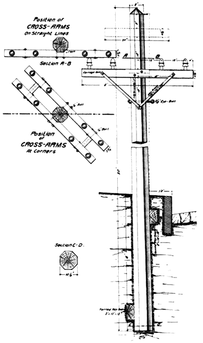 |
| Fig. 6. -- Poles and Cross Arms. |
The span cables are of stranded wire 5-16 in. diameter, made of seven soft drawn No. 12 galvanized steel wires without a core, and are secured to drop-forged eyebolts 5/8-in. diameter, which pass through the poles and have a nut and washer on the opposite side of the pole from the tracks. The eye-bolts are sufficiently high to hold the trolley wires 18 ft. above the rails, as shown in Fig. 3. The bolts have sufficient length of thread to allow 4 ins. of slack to be taken up after the spans are in position and the poles well set. The trolley wires are No. 0 B. & S. gage, hard-drawn copper, and have 97% of the conductivity of pure copper. They are thoroughly insulated from their supports. The wire was put up in as great lengths as could be conveniently handled, being run off the reels upon which it was carefully wound, and handled so as not to bend, kink or scratch it. Joints in the trolley wire are made by splicing-ears of the best and latest style, and no joints occur in or near sharp curves. The line insulators are of the latest style. On tangents they are General Electric mechanical clips. On sharp curves and at such other points as the engineer directed, the ears were soldered to the trolley wire.
The trolley line is double-anchored at all grades and curves, and at intervals of at least 1,000 ft.
The wire used for anchor lines is the same as that used for span wires. Each pole to which the wire is anchored is back guyed to the next pole. Eye-bolts are used in all cases, no guys being allowed to be wound around any pole or tree. Pull offs are used at all curves, overhead switches, etc. to properly center the trolley wire over center of track. All overhead-frogs are well guyed. Some form of insulator is used in each anchor wire, two or three feet from the anchor-clamp.
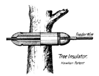 |
| Fig. 7. -- Tree Insulator. |
Lightning-arresters are put upon the poles about 1,500 ft. apart and are attached to the bond-wires of the track and to the feeder-wire connections. Tree-insulators, Fig. 7, are used to provide against losses and dangers which result from abrasion of feeder wires.
The trestle shown in Fig. 8 was designed as a temporary expedient to get across the valley of Third River until the county of Essex should proceed with the rebuilding of the wooden bridge across the valley. In regard to the absence longitudinal bracing. Mr. Wise explains that believing that it might be two or three years before a new bridge would be built, the engineers in their first plans provided for longitudinal diagonal bracing waling, etc., but that as soon as the company was informed that the county proposed to at once proceed with the construction of the bridge, the engineers were requested to cut down the bill of timber as much as possible, and, as the end bents would be well covered with the embankment, the longitudinal bracing, etc., was left out. While the materials for the trestle were provided and on the ground, and the approaches graded, the trestle was not erected, because it was seen that the new stone arch would in all probability be completed before the franchise in Belleville township could be secured, and until this was done nothing would be gained by erecting the temporary trestle The stone structure is now complete and ready for the tracks of the electric railway company. It has three arches of about 45 ft. span and was built according to the plans of Mr. James Owen, M. Am., Soc. C. E., County Engineer of Essex county. The cost of constructing the stone bridge and filling the valley to a height of over 22 ft. has been divided equally between the county and the electric railway company. The trestle was to be 225 ft long, with frame bents 12 ft. 6 ins. c. to c., and a 25-ft. truss over Third River. The double tracks were to be gauntleted across the structure, as shown. Fig. 9 shows some of the details of the trestle and truss.
A curve of 40 ft. radius, turning a right angle at a street corner and having its ends suitably transitioned to 200 ft. radius at the tangent points, is shown in Fig. 10.
