[Trade Journal]
Publication: Electrical World
New York, NY, United States
vol. 73, no. 3, p. 116-119, col. 1-2
An Operating View of High-Tension Insulators
Severe Operating Conditions That Have Caused Failure of Line Insulators - Later Designs of Pin
and Suspension Types Promise to Solve Insulator Problem for
Some Years to Com.
BY P. ACKERMAN
Electrical Engineer Toronto Power Company
RECENT improvements in insulator design and manufacture have resulted in the production of insulators which appear to meet the severe tests of operation on the line with reasonable success. The porcelain disks or petticoats of modern design are thicker and of such shapes that better distribution of the electric field is obtained, decreasing the possibility of destruction from power arcs and abnormal voltages. It is thus the opinion of the writer that so far as design is concerned the problem of the line insulator can be considered as solved for a considerable time to come. In the matter of quality, also, owing to improvements in design and manufacturing, a more lasting insulator should be obtained than any produced in the past.
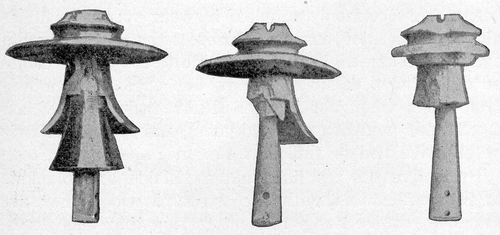 |
| Fig. 1 - Appearance of Three Pin Insulators After A Lightning Storm |
The functions of line insulators may be stated as follows:
(1)To resist flashover under the worst possible weather conditions and under the most serious over-voltage which may be set up due to internal surges.
(2)To resist puncture direct from line wire to pin through the head, whenever flashover of the insulator is inevitable because of severe lightning surges.
(3)To resist power-arc destruction whenever lightning flashes over the surface of the insulator.
(4)To resist all possible mechanical strains from abnormal weather conditions.
To appreciate more clearly the importance of these functions it will be necessary to review the abnormal operating conditions to which line insulators may be subjected.
SEVERE CONDITIONS IMPOSED ON LINE INSULATORS
Internal surges are set up owing to switching, accidental grounds of one phase on non-grounded three-phase systems and sudden load changes in a long-distance transmission line. Such surges may for a brief period cause a voltage rise up to twice normal. To avoid line short circuits and service interruptions it will be necessary therefore to provide an insulator which will not flash over under the most trying weather conditions at less than twice normal operating voltage.
Lightning surges may be of any magnitude, so that it is impossible for commercial reasons to provide sufficient insulation to resist lightning flashover. It has been found that it requires more than 330,000-volt insulation before immunity from lightning flashover can be expected. Since rain is always combined with lightning storms, it means therefore that the line insulators will have to have a wet flashover in excess of 300,000 volts before immunity from lightning flashover is possible. This insulation value, however, is only reached by insulators used for systems operating at 100,000 volts and above, and it will be at once realized that no such excessive insulation can be applied to lower voltage systems merely for the sake of immunity from lightning flashover. Systems operating at less than 100,000 volts will thus have to submit to occasional flashover from lightning, and it is essential therefore to provide such insulators that this flashover will not do sufficient harm to disable the line permanently. To attain this object the first necessity is that the insulator be puncture-proof; in other words, that the insulator be built in such a way that it will flash over around the outside, through the air, rather than pierce a hole through the porcelain directly from wire to pin. A puncture will invariably result in such severe destruction of the insulator that the line will be disabled until the insulator is replaced, which may mean hours of service interruption-the time necessary to locate and replace the insulator.
The destruction from flashover, with properly designed insulators, will generally be limited to broken skirts, leaving sufficient flashover distance to withstand normal operating voltage after the arc has been extinguished by momentarily interrupting the line; as a result service can be quickly restored, causing a few minutes' interruption only. The better the insulator is able to resist the power arc, the less danger of permanently disabling the line will exist.
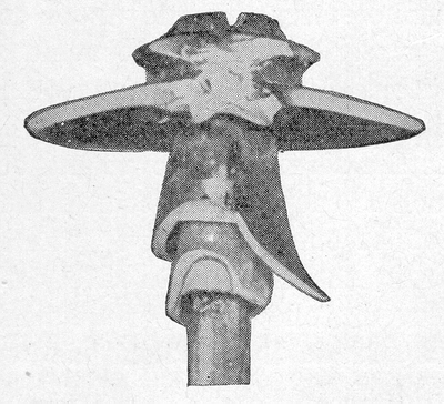 |
| Fig. 2 - Pin Insulator Destroyed by Power Arc of 500 Amp. Lasting Five Seconds |
Weather conditions greatly influence the flashover value of insulators and accordingly have to be seriously considered in determining the necessary safety factor of flashover to normal operating voltage. Rain will reduce the flashover considerably compared with dry conditions. Localities with dust and smoke may cause a coating on the insulators which in itself is not conductive but may cause flashover in the presence of rain or mist.
Sleet and wind chiefly determine the mechanical requirements of the insulator.
Temperature changes from the severe winter cold to the summer heat, or the concentrated heat of the summer sun striking the insulator on one side only, or sudden cooling of porcelain from rain after extreme heat, all put severe internal stresses on the porcelain, tending to crack the individual shells.
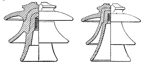 |
| Fig. 3 - Old and New Designs of Pin Insulators (New One at Left) |
Moisture in the atmosphere may penetrate into surface pores or gradually work its way through complete channels of capillary porosity in the porcelain, and this finally will cause puncture.
It thus follows that an insulator, to be considered satisfactory from an operating viewpoint, should have a wet flashover of not less than twice normal operating voltage. It should resist puncture and power arc and withstand all weather influences without weakening electrically or mechanically.
In the following paragraphs it is attempted to review in detail the causes and possible remedies of puncture and power-arc destruction, although it must be said that such review must remain very incomplete for the reason that many causes are obscure and in regard to others the opinion of engineers varies greatly, depending on their local experience.
CAUSES OF AND REMEDIES FOR PUNCTURE
In the early days of insulator design it happened quite often that the flashover distance over the insulator was made greater than the thickness of the porcelain permitted with the result that the porcelain would puncture rather than flash over. Moreover, many insulators of the older designs had such bad electrical stress distribution that severe corona was noticeable at comparatively low voltages, causing a gradual redistribution of the electrical stresses, individual skirts being overstressed and punctured when subjected to flashover voltage. With the practice of testing each insulator for at least momentary flashover, such bad designs are no longer tolerated, and it may be said therefore that with very few exceptions all insulator designs found on the market to-day are provided to stand at least momentary flashover.
Porcelain cannot be manufactured with accurate uniformity of product. The result .is that even with an ample design no assurance exists that the individual insulators will actually come up to the expected puncture strength. No insulator can be trusted therefore to flash over rather than puncture unless actually tested. In former days insulators had a routine test below flashover before leaving the factory, and in most cases the test they received was in regard to the future operating voltage rather than the flashover voltage. As a result they offered no assurance of resisting puncture in case of lightning. To-day the standard practice is to subject any insulator for a shorter or longer period to flashover voltage so that failure of the later type of insulators in case of flashover cannot possibly be attributed to a too easy factory test.
It happens, however, that even insulators which have withstood momentary flashover at the factory may be found to puncture in service without any apparent reason. The causes of this apparent deterioration in service are not quite cleared up yet despite exhaustive investigations of late years. Still, some of these causes have been established. For others some theories have been advanced based on the appearance of the defects. Doubtless similar troubles occur on both pin and suspension insulators, but the suspension insulator seems to be particularly sensitive to deterioration.
The following are the best known causes and theories explaining deterioration:
1. Unglazed porcelain seems to be all porous. The porosity may be slight surface porosity only extending from very fine surface cracks toward the inside, forming when filled with moisture projected needlepoints and thus reducing the effective puncture value or it may be capillary porosity forming capillary channels extending through the whole porcelain thickness, the pores being so fine that it takes, considerable time, possibly years, until moisture works its way through and finally causes puncture; or again porosity may be so great, owing to improper firing or bad clay, that the moisture from the cement will instantly form a moisture path detectable by the megger.
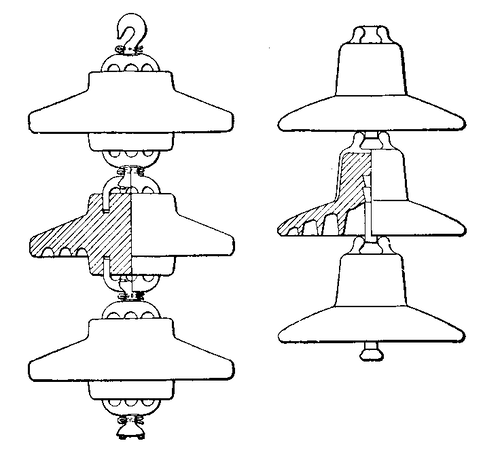 |
| Fig. 4 - Radical Change in Design of Suspension Disks (At Left) |
Unfortunately no means exist to determine the exact state of porosity, and although a severe flashover test after assembling will weed out all the badly porous material, it does not offer a permanent assurance that the material will be non-porous, as capillary porosity may appear only after years of service. Opinions among engineers differ widely as to the importance of this cause. It is the experience of the writer that porosity is one of the most important factors to be considered, although it may be said that the porcelain of the last few years seems to be considerably improved. A remedy to eliminate moisture penetration into pores can be found in glazing the vital head part, thus making it moisture-proof.
2. Observed cracking of porcelain may be due to various causes. The most advanced theory is that it is caused by the unequal expansion of porcelain, cement and iron due to extreme temperature changes. This has no doubt been a serious trouble in suspension insulators of past designs. However, it does not explain the puncture of later designs, in which provision has been made for pin and cap expansion and setting of the cement in a steam bath, and which show in design tests the ability of resisting successive temperature changes from iced water into boiling water.
Another theory is that the swelling of cement, when filling with moisture, may crack the porcelain. This could possibly happen in a very damp climate. However, the writer has been unable to find any evidence so far to support this theory. He had opportunity on several occasions to examine carefully the cement on insulators which have been in service for over ten years and has always found the fine radial cracks in the cement which apparently had formed during the shrinkage when originally set. Should any swelling take place, we should expect this space to disappear. But, assuming that any such effect could result, the proper remedy should be thick porcelain and small cement space so that the force of the swelling cement would be small and the mechanical resistance of the porcelain great.
Continuous mechanical vibrations and sudden shocks from wind and whipping wires may largely be the cause of cracks observed. This theory appears plausible, particularly in consideration of the fact that the combination of iron, cement and porcelain, as used in pin and suspension insulators, forms an extremely unrealistic arrangement, and in addition porcelain is very sensitive to shocks.
A link between porcelain and cross-arm giving a kind of cushion effect to dampen the shock would be very desirable to eliminate such trouble. In pin-type insulators this remedy is found by applying steel pins with a lead thimble and in suspension insulators by using some kind of alloy in place of the cement.
Natural internal stresses in the porcelain due to drying and firing may offer an initial weakness which, aggravated by any of aforesaid causes, may develop cracks. Such internal stresses should be eliminated by avoiding sharp bends in shaping the individual porcelain pieces. This may be one of the principal reasons why the standard unit is frequently found cracked in the corner where disk and head join.
AVOIDING POWER-ARC DESTRUCTION
It appears that far too little attention has been given to this subject in the past as a large number of troubles with pin-type insulators during lightning storms could be traced to power-arc destruction rather than to puncture.
The old designs of pin insulators, and to a large extent also later designs, are absolutely unfit to resist a heavy power arc for any length of time. The only thing that saves them from very severe destruction is the fact that the wind generally blows the arc away from the insulators. The main reason for this sensitiveness to power-arc destruction is the thin shells and the very steep and narrow skirts in which the hot gases get caught, finally breaking up the petticoats.
The short-circuit current on transmission lines will vary greatly according to location of the short circuit relative to the power house, the generating capacity of the system and the operating voltage; but on any larger system it will exceed 1000 amp. and in effect may amount to many thousand amperes, so that it will readily be understood that the heat of the arc will be very considerable.
The most severe destruction is experienced if the arc-over takes place in quiet air. Under these conditions the arc will persistently envelop the whole insulator and usually break up all petticoats.
Fortunately the arc is very easily moved by the least wind into its own direction, thus bending the arc out and carrying the bulk of the heat away from the insulator. With the wind blowing at right angles to the line the danger of heat destruction is still quite pronounced because the arc terminals remain persistently at top and bottom of the insulator, endangering particularly the bottom petticoat. The least damage from power arc is generally experienced with wind in the direction of the line. In this case the arc is blown along the line wire; that is, the grounded arc terminal stays on the cross-arm and the other one moves rapidly along the line wire, thus stretching the arc and moving the flame away from the insulator. With heavy wind the arc has even a chance to extinguish itself.
With only the slightest wind blowing there is generally a fair chance to save the insulator from total destruction. After the arc has been extinguished sufficient insulation may be left to resist normal operating voltage, provided that the circuits are cleared instantly after the short has developed and provided the insulator is sufficiently rugged to resist power-arc destruction.
It will be realized that thick porcelain will be of prime importance to resist power arcs, as the heat will only affect the surface, and the more massive the body the better the porcelain will resist cracking.
For years there have been means suggested to deflect the power arc away from the insulator before any damage is done. Nicholson's arcing ring was one of the first of these devices. Horns of various forms and in different positions also have been suggested and partly put in use. They have, however, never found extensive use, this being probably due chiefly to the complication involved in mounting and because most of the troubles in the past were punctures and not plain power-arc destruction. But even with the development of puncture-proof insulators it is unlikely that this device will find extensive use since thick porcelain insulators assisted by instantaneous relay protection and arc extinguishers will be able to withstand flashover.
COMPARISON OF OLD AND NEW DESIGNS
In order to show the striking difference between old and new designs of pin insulators the following features are pointed out:
(1) Thick shells assure greater resistance to power arc, temperature changes, handling, etc.
(2) Rounded heads should reduce internal stresses from firing and thus reduce danger of cracking from external forces.
(3) Sanded joints permit smooth surfaces and accordingly reduce danger of surface cracks.
(4) Small cement space coupled with thick porcelain eliminates danger from swelling cement if any such danger exists.
The present type of suspension insulator has caused extremely severe trouble, and despite the many improvements which have been made and suggested it appears that the insulator will retain certain inherent weaknesses. A new insulator of this type has been put on the market, however, which promises to become a serious competitor to the suspension insulator now in use, as it embodies many important features.
The advantages of this new suspension insulator over older designs may be summarized as follows:
(1) the disk is of extremely heavy bulk and accordingly should resist power-arc destruction.
(2) The design is such that temperature changes should have very little effect.
(3) The iron spider is cast into the porcelain body by means of some low-melting and comparatively soft alloy which should act as a damper of shocks.
(4) The electrostatic field is so nearly ideal and the puncture thickness between electrodes so excessive that the unit should be puncture-proof with porcelain of fair quality.
The mechanical strength of the unit is somewhat lower than that which is obtained from the ordinary type of suspension unit, but it offers, on the other hand, the advantage that its guaranteed strength can be verified on each unit before leaving the factory. This cannot be done on the cemented insulator.
PIN AND SUSPENSION INSULATORS COMPARED
The general opinion among engineers not closely connected with the problem of line insulators is that the pin-type and suspension-type insulators are competitors. This assumption is not quite correct as they supplement rather than compete with each other, excepting in the application for line voltages of 70,000 volts to 110,000 volts. In this application it depends largely on the local conditions, the judgment of the engineer and, it might almost be said, the taste of the engineer which type will be adopted. Below 60,000 volts pin insulators are used almost exclusively except in cases where the line may be prepared for future higher voltage. Above 110,000 volts suspension insulators are used almost exclusively.
It may be of interest to indicate why the two types are suitable for different voltage ranges. Pin-type insulators when built for wet flashover values exceeding 160,000 volts become extremely large, heavy for handling and expensive, and the increase in weight and cost seem to be far out of proportion compared with the increase in the wet flashover value. Suspension insulators, on the other hand, can be built for practically any wet flashover value up to 400,000 volts at a proportional increase in weight and cost by the addition of extra units. Whenever a wet flashover of more than 160,000 volts is considered necessary one will be forced, therefore, for reasons of practicability and economy, to adopt the suspension type.
The pin-type insulator is generally recognized as preferable because fewer troubles are experienced from wind and sleet, due to the rigidity of the support. The suspension insulator therefore may be termed a necessary, though undesirable, substitute for the pin insulator where wet flashover voltages in excess of 160,000 volts are required, as in the case of lines operating at voltages above 100,000.
As pointed out previously, the suspension insulator is found cataloged for wet flashover voltage values as high as 400,000 volts. There does not appear to be any reason why this value could not be increased to 450,000 volts or 500,000 volts by increasing the length of the string. At a safety factor of two this would correspond to an operating voltage of 225,000 volts to 250,000 volts, so that it may safely be said that the line insulation problem is solved for operating voltages as high as 250,000 volts, which is rather more than is anticipated at this time.
MATERIALS FOR INSULATORS
The serious trouble experienced with porcelain insulators, their uncertain quality when leaving the factory and the brittleness and low mechanical strength of porcelain have always inspired the engineer to find some substitute of more ideal qualities.
Molding materials, which are so successfully used for indoor insulating purposes, have often been suggested for line insulators. The reason why such materials will never be satisfactory on the line is because they will not stand a power arc without charring, and as a result whenever flashover occurs the line will become disabled until the insulator is replaced. Surface leakage in rainy weather may also be sufficient to char the surface of the insulator and thus leave a permanent leakage path which finally will cause trouble.
This indicates clearly that the insulator surface must be made of refractory material if the insulator is to be lasting at all. Various kinds of glass, boro-silica, fused quartz and other materials have been recommended; but the cheaper glasses, which possibly could compete with porcelain in regard to price, are generally more brittle and cause more trouble, while boro-silica and fused quartz, though in many respects advantageous, have so far been too expensive to come into serious consideration.
Considering the improvements made in the manufacture and design of porcelain insulators and the cheapness of manufacture, it is the opinion of the writer that porcelain will maintain its position as the first and almost only material for line insulators.
THE conditions now confronting us are so unprecedented that we must guide ourselves rather by the eyes of prophecy than by what has been done in the past. We can hardly expect large reductions in the prices of material and labor for some time because the prices of labor always fix the cost of material. Consequently public utilities must depend upon expert management for the present-Henry L. Doherty.
Taken from a paper presented by the author at a recent meeting of the Toronto Section, A. I. E. E., with slight revision.
