[Trade Journal]
Publication: Western Electrician
Chicago, IL, United States
vol. 43, no. 2, p. 21-23, col. 1-3,1
SINGLE PHASE TRACTION IN GREAT BRITAIN.
(From the London correspondent of the Western Electrician.)
The first single-phase railway in Great Britain has just been put into operation by the Midland Railway apon its branch line connecting Heysham, Morecambe and Lancaster on the northwest coast of England. The line is somewhat in the nature of an inverted Y, with Morecambe at the apex and Heysham and Lancaster at the extremities of the left and right arm, respectively. The distance from Heysham to Morecambe is five miles, and from Morecambe to Lancaster four miles.
| |||
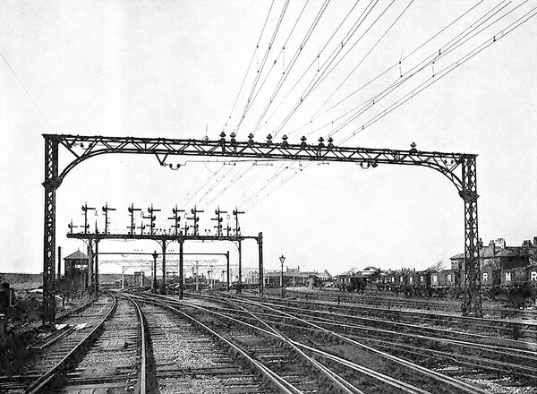
| Wide - Span Supporting Bridge for Overhead Construction for First Single-Phase Railway in England. |
It may be pointed out that the company has selected this line for carrying out the experiment of testing the suitability of single-phase traction for heavy railway working in preference to a busier section, for the reason, among others, that the section in question is subject to very severe weather conditions, so that a conclusive test should be obtained. Taken in conjunction with the experiment by the London, Brighton and South Coast Company near London, the results should be of some practical value to railway managers who are now wavering as to the system which should be adopted.
Overhead Construction.
Dealing first with the overhead construction, it will be noted that the type of suspension is similar to that adopted upon the Hamburg-Altona Railway in Germany, the patents for which are held in England by Siemens Bros., who are carrying out the work in this instance. The system has been modified, however, by a new type of catenary wire suspension designed by one of the railway companys engineers. The line passes under several bridges, mostly of the arched shape, and the clear clearance of these has been given considerable attention. The use of a single bow trolley for traveling in both directions necessitates the bow being symmetrical about the center of the car, necessarily bringing if close to the structure of the bridge. In order to get through at all, it has been necessary to take the contact wire well out toward the center of the arch, so that it may come down low and yet be clear of the loading gauge and so that the other side of the bow may clear the structure properly.
The contact wire is of figure 8 section, and the height from rail level varies from 18 feet 3 inches in the open to 13 feet 3 inches under bridges. It is suspended from short loops about four inches long from a steel cable or auxiliary wire; upon which these loops are movable. In turn, the auxiliary wire is held by the main catenary cables, of which there are two, clipped together throughout their length, except for about three feet on either side of the insulator, where they divide to pass through the grooves of a ring, the grooves being on opposite sides of the insulators. The catenary is thus free to move for this distance, and this equalizes the strain due, to unequal loading, and experience has proved that it is at the same time secure in the case of the breaking of the wire.
The section switches which are provided to isolate the up and down lines or the different sections are of the double-break air pattern, and are fixed on top of the poles supporting the cross suspension for the overhead construction . Each section switch is, in addition, duplicated, and the connection from one contact wire to the section ahead is accomplished by means of a short section of switch wire which requires to be connected to the two contact wires before the line is switched through at this point. In this way a duplicate break is obtained, and, more important still, there is a short length of line into which a car can run without bridging by means of its bow two sections which it was supposed might require to be isolated.
A separate steel cable connects the wire-supporting bridges together, and this is grounded every half mile, the same earth plates being used for horn lightning arresters, thus diminishing the number of earth plates requiring attention and at the same time giving better security from danger from leaky insulators, so far as the poles are concerned. It is interesting to note that this grounded steel cable has been erected between the contact wires and the telegraph wires, which are open on side of the line, and it is believed that this has had a great deal to do with the reduction of electrostatic induction from the contact wire. The object aimed at has been to avoid putting underground all the overhead telegraph and telephone wires.
Although at one or two places it has been necessary to erect steel lattice poles and lattice-girder supporting bridges, owing to the big spans, such as that shown in an accompanying illustration, for the most part creosoted wooden poles have been used. Where wooden poles are used the cross suspension pieces are made of two angle-irons brought together at the ends, but so fitted that there is a great range of adjustment of the insulator position without any necessity for drilling.
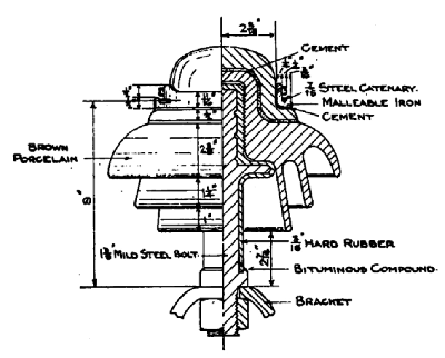 |
| High-Tension Insulator for First Single-Phase Railway in England. |
The type of insulator was decided upon after ascertaining from experiments made by Siemens Bros.' staff the minimum distance at which, a 6,600 volt, 25-cycle circuit would maintain an arc in the heaviest weather. In order to get what amounts to double insulation with one insulator, the steel bolts supporting the insulators are encased with ebonite, in addition to which, in order to get extra strength, the company preferred to make the insulators in two pieces.
An interesting point arose in connection with the bonding of the track. Only the outer rail on each line is bonded throughout, the bonds being of the Forest City type, and although very great care was taken to prevent moisture getting into the holes While they were being drilled, and although after completion all the bonds were found to be first-class, yet the tests carried out afterward showed a distinct difference in resistance between those bonds made during dry weather and those made during damp weather.
The rails are grounded in the sea at Heysham Harbor by duplicate copper earth plates, while at Morecambe they are grounded at the pier by plates which have been dropped in a large cast-iron caisson. At Lancaster they are grounded to the cast-iron columns of the bridge which rest in the bed of the river. As already indicated, the potential of the overhead wire is 6,600 volts, 25 cycles, single-phase alternating current.
CAR EQUIPMENTS.
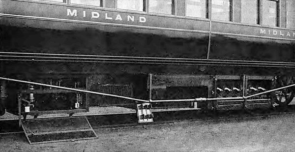
At present the rolling stock, which has been built by the railway company, consists of three trains, there being three motor cars, two having Siemens equipments and one a Westinghouse equipment. There are also four trailer cars, while in addition a number of cars will be used for workmen's and freight traffic. Driving equipments have been fitted at both ends of the motor cars. As will be seen from the illustrations, the motor cars are of the corridor type, the extreme lengths and widths being Go feet and nine feet. Each has a seating capacity of 72 passengers, the middle seats being arranged transversely and the seats at either end longitudinally. The lighting is from the line current, as is also the heating of the motor cars; the trailer cars have not been fitted in this way yet, however, as their extended use during the winter months is not contemplated. On the trailer cars, which have a length of 43 feet and a width of nine feet, the seats are placed transversely throughout, the accommodation being for 56 passengers.
| |||
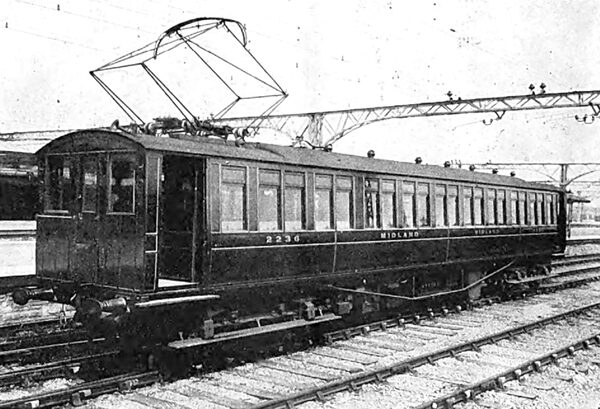
| Siemens Car, Showing Bow Contacts. |
| |||
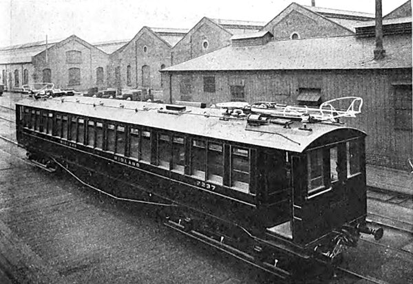
| Westinghouse Car, Showing Pantagraph Bow. Motor Cars in Use on First Single - Phase Railway in England. |
The specification of the electrical equipment of the cars called for two 340-volt motors per car, both to be carried on one truck. The normal train was specified to consist of a motor car and two trailers. The specification further made it a condition that the different equipments of the two contractors should be capable of being worked, from the same master controllers. Two 180-horsepower motors are used on each Siemens car and two 150-horsepower motors on the Westinghouse car. The Westinghouse car is fitted with standard electro-pneumatic control, modified, in order to enable it to work with the all-electric control of the Siemens car.
As will be seen from the illustration, the Siemens cars are provided with two collector the reason that it was found impossible to get the firm's standard inverted pantagraph type of bow into the space available under the bridges; there is a small auxiliary bow controlled by parallel motion. The disadvantage of this type is that it requires balancing by a wind screen, as will be noticed. On the other hand, the Westinghouse company has adopted its standard type of pantagraph bow collector, and only one is used.
The roofs of all the cars are covered with a grounded wire netting whose function it is to throw out the station circuit-breakers in the event of the overhead wire coming down on the roof. On the Siemens cars the high-tension wire proceeds into the high-tension chamber, the door of which is mechanically interlocked with the bows, so that it cannot be opened unless the bows are down. The low-tension wiring is not carried in metal tubing, for fear of eddy currents, but is substantially surrounded with metal.
| |||
| High-Tension and Contactor Chambers Are Shown Open. Underframe of Siemens Car Used on First Single-Phase Railway in England. |
The equipment of the Siemens cars consists of the two motors, the main transformer, the auxiliary transformer, preventive coil, the commutating transformer, high-tension circuit-breaker and fuse in the main transformer circuit, high-tension fuse in the auxiliary transformer circuit, contactor, motor fuses (which also act as motor cut-outs) and low-tension fuses in the circuit feeding the control, and also a low-tension fuse in the circuit feeding the fan. No fuse has been placed in the brake-pump main circuits, so that if anything goes wrong with the pumps, the main fuse will be blown and the car cannot be worked.
The Westinghouse equipment consists of motors, transformers and auxiliary transformers, preventive coil, high-tension circuit-breaker in main circuit, fuse in auxiliary high-tension and low-tension circuits, contactors and control gear. The motors are ordinary series compensated, without any special commutating device other than the commutator resistance leads. It is said that the commutating performance of these motors on the line is as good as, if not better than, most heavy direct-current traction motors, while the commutator remains in quite as good running order as that of any such motor. The same good qualities are claimed for the Siemens motors as the result of trials.
TRAIN PERFORMANCE.
With regard to the performance of the trains on the road, in a test with a two-car train weighing approximately 58 tons, made incidentally in the course of ordinary running, one of the Siemens cars attained speeds of 30 miles an hour in 41 seconds and 48 miles an hour in 80 seconds, and a free running speed of 60 miles an hour in 160 seconds, starting and running for 440 yards, on an upgrade of 1 in 200, there being, however, thereafter about 100 yards of level and then a down grade of 1 in 500 for 1-1/2 miles; this portion of the line is also very considerably curved.
POWER-STATION APPARATUS.
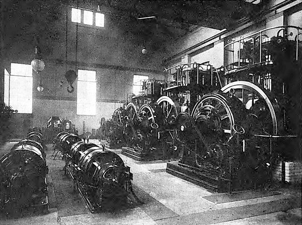
The power supply for the line is furnished from an existing gas-driven generating station at Hey-sham, used in connection with the lighting and power requirements of the railway company. Mond gas producers are used, and the equipment of the station hitherto has been three 250-horsepower three-cylinder Westinghouse gas engines, driving 150-kilowatt, direct-current, 460-volt generators. In connection with the traction scheme, however, an additional 350-horsepower Westinghouse gas engine driving a 235-kilowatt generator of the same make has been installed, in conjunction with two motor-generators.
| |||
| Heysham Gas-Engine Power Station Supplying Current for First Single - Phase Railway in England. |
From the nature of the traffic the demand on the station will be of a very "peaky" character. During these "peaks" the whole possible output of the machinery at work in the station must be utilized, and the intention is for the engines, whatever the actual load they may be working on previous to heavy loads coming on, to work up to their full overload capacity, which is about 20 to 25 per cent. in the case of the old, and 10 to 15 per cent. in the case of the new sets, before the storage battery, which is a part of the station equipment, is called upon to discharge heavily. The latter will, however, be called on to work up to its full one-hour rate of 750 to 1,000 amperes.
The old battery booster not being large enough for these discharges, a new one has been installed. A difficulty was, however, found in that the pressure dropped badly as the loads increased. This had been compensated for by hand regulation of the excitation, or else, during "peaks," the generators continued to work at their previous loads, and the battery supplied the excess, both courses being inadmissible under the new conditions. Compound winding in the usual way was an extremely expensive remedy, since, as the copper necessary for full excitation was already on the fields, new series coils would be excessively large and heavy, added to which was the trouble of entirely dismantling the machines.
A very simple solution was found in fitting exciters, each mounted on the engine bedplate, and compound windings being fitted on these exciters and varying their voltage, and consequently that on the main generator fields, so that the existing copper on the latter was fully utilized. This not only proved a much cheaper arrangement, the exciters being only of three kilowatts capacity and of fairly high speeds, but enabled the whole change to be made in the course of a week, obviating any dismantling or any serious stoppage of the generating sets.
The new booster, with a comparatively low continuous rating, satisfactorily commutates the "peak" discharges up to 750 to 2,000 amperes; and it can be set to make the engines work up to their overloads as above, or to work under practically any other conditions, without any serious drop on the bus-bar voltage.
The new generating set is of the Westinghouse latest type of gas engine, having three cranks with three sets of cylinders, two in tandem in each case. Its speed is 300 revolutions per minute and its lubrication forced.
The specification for the motor-generators called for the machines to be each capable of a continuous output of 150 to 200 kilowatts, with a temperature rise of 80° F., but they were also called upon to be capable of safely carrying output overloads of 600 kilowatts instantaneous, boo kilowatts for half a minute, 500 kilowatts for three-quarters minute and Sod kilowatts for 2-1/2 minutes, and were required to be also tested under a regular cycle of these overloads, with underloads in between, for eight hours. Further, they were required, with the assistance of external means, if necessary, to restore the pressure to normal within seven seconds of the coming on or throwing off of loads up to 600 kilowatts at 0.8 power factor or 300 kilowatts at power factors down to 0.3. The machines of the. Electric Construction Company were finally selected.
The switchboard has been designed and constructed by the railway company, the instruments being of the Westinghouse company's make. Each of the motor-generators is supplied from the low-tension bus-bars through a no-voltage and overload circuit-breaker. The shunt circuit is excited through a separate double-pole knife switch with kicking contacts and resistances. Starting resistance is cut out by means of a set of knife switches. By means of a throw-over switch these can be used to start either set of the machines, a heavy triple-bladed knife switch being thrown in finally when the machines are fully started up, connecting them direct to the bus-bars. On the alternating-current side each alternator is connected up to the bus-bars by a hand-operated oil switch, and the current passes from the bus-bar through duplicate automatic circuit-breakers to duplicate feeders passing out through overhead lines. All the circuit-breakers, both high and low-tension, have time-limit devices. The exciter shunt fields of the alternators are also connected through double-pole switches with non-inductive contacts and resistances. The high-tension apparatus is contained in a lockfast expanded metal chamber placed over and at the back of the actual switchboard, the switches being operated from the handles of the latter through rodding. The door of the high-tension chamber is interlocked with the holding up coil of the motor circuit-breaker, so that unless the door is closed neither motor-generator set can be started, while if it is open during running everything stops.
I have to thank the officials of the Midland Railway. Company for the illustrations and material contained in this article.
