[Trade Journal]
Publication: Western Electrician
Chicago, IL, United States
vol. 39, no. 1, p. 1-2, col. 1-3
The Building of the Elgin-Belvidere
Electric Railway.
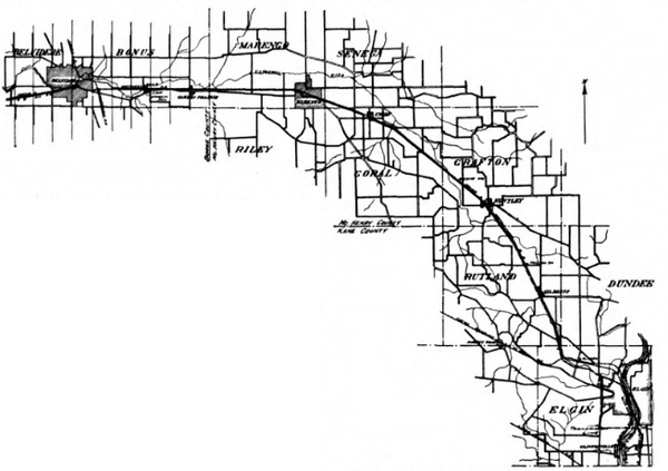
Located in a wealthy and prosperous section of Illinois, the electric railway of the Elgin and Belvidere Electric Company, which is now getting well on toward completion, will begin operations with every indication of success. The route taken by this road is well shown in the map. The cities of Elgin, 22,500 population, and Belvidere, 7,000 population, form the terminals of the line, which is about 36 1/2 miles long, and there are located along the route nine other cities and villages. The system is some 40 miles northwest of Chicago and will ultimately form the connecting link between the Aurora, Elgin and Chicago third-rail line and the Wisconsin system connecting Beloit and Janesville, and ultimately Madison, with Rockford and Freeport, Ill. Arrangements have been made hereby passengers and freight will be carried jointly by the three roads. The population on and immediately tributary to the Elgin-Belvidere line is estimated to be about 52,000.
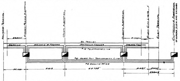
Power for operating the cars between Elgin and Belvidere will be furnished by the Aurora, Elgin and Chicago. The transmission-line voltage will be 26,400, which will be stepped down and transformed from three-phase alternating current to direct current at three sub-stations, located at Garden Prairie, Union and Gilberts. The sub-stations equipped with rotary-converters and the necessary transformer and switching apparatus. The buddings also contain passenger, freight and baggage rooms.
Though the line is not yet completed, there are many interesting features about the construction work and the equipment which is being installed. The accompanying illustrations are views taken along the line as the work progresses, and the diagrams show the details of the construction.
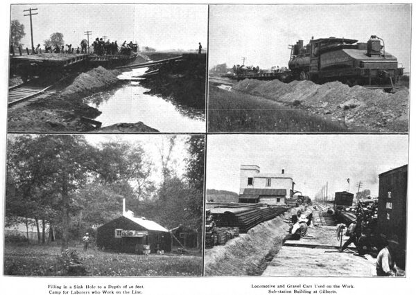
A few details of the roadbed will first be given. The width of the roadbed at the grade line is 14 feet for single track and 27 feet on sidings. As shown in one of the pictures, the laborers while working grading the line were lodged in comfortable tents or shanties close to the scene of the activities.
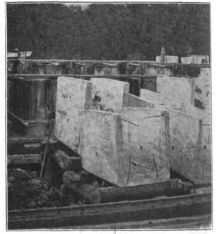
Bridges are pile trestle and reinforced concrete. At the Kishwaukee River, near Belvidere, one of the largest bridges was built, comprising four spans, 87 feet six inches center to center of the piers. The bridge is designed to carry regularly two standard 40-ton interurban cars. Where small quantities of water must be carried through the roadbed, tile drains are used, and in all other details the work is being done in a manner conforming to steam-railroad practice.
| |||
| The Building of the Elgin-Belvidere Electric Railway. |
One of the illustrations shows where a fill was made in a marsh or sink hole. Work at this point was seriously delayed, owing to the almost impossible task of filling up the sink hole, which was 40 feet deep down to the clay bottom, being filled with an unstable soil of decayed vegetation. Though the bog was perfectly level at the start, the filling-in process, as the work progressed, slowly pushed the loose peat up on each side of the road bed into the form of an embankment, as shown in the picture.
The track construction is of a durable nature. The ties are of tamarack, hemlock and cedar. The rails, in 33-foot lengths, weigh 70 pounds to the yard. Ballasting of the track has not yet been done, as shown in the pictures. Such parts of the track as are on private right-of-way will be ballasted with gravel. On public highways or on the streets the space will be graveled or paved, as required by ordinance.
Line construction as exemplified on this road is of a high order. The high-tension transmission lines, direct-current feeders and telephone lines are carried on one pole line. The brackets supporting the trolley wire are also mounted on these poles, as shown in one of the accompanying diagrams.
Timber used for the cross-arms is of thoroughly seasoned, straight-grained southern pine or Norway pine. The high-tension cross-arms for the three- phase line are 3 3/4 by five inches in cross-section, those for the low-tension feeders being 3 3/4 by 4 1/4 inches. The high-tension cross-arm pins are of wood, with porcelain base, and are not less than 13 inches in length. The pins for the low-tension cross-arms are constructed with a wood top and a half-inch galvanized steel bolt.
All insulators are of glazed porcelain. Those for the high-tension work are made in two piece-cemented together, and are about eight inches in diameter and seven inches high, with a grooved top for a one-fourth-inch conductor. These insulators are designed for a working voltage of 26,400, and are tested at not less than 70,000 volts. The low-tension insulators are constructed in one piece, with double petticoats about four inches in diameter and three inches in height, with a top groove for a 1 1/8 inch conductor.
The high-tension line wires are equal in conductivity to a No. 6 hard-drawn copper wire, and were shipped in lengths not less than one mile. The low-tension wires are of two sizes, the larger size equivalent to a 500,000-circular-mil copper cable and the smaller size equivalent to a 300,000-circular-mil copper cable. The trolley wire is a No. 000.
As will be noted in one of the diagrams, the trolley wire is supported over the track by a horizontal bracket fastened to the poles carrying the transmission and low-tension lines. These brackets are made of 1 1/2-inch structural-steel tubing nine feet long. They are equipped with a five-sixteenths-inch stranded span wire provided with two strain insulators. All trolley hardware is suitable for a No. 000 grooved trolley. The trolley hangers are of approved style, with galvanized malleable-iron yokes. Clamping ears are of the screw-clamp type at least 12 inches long. Strain insulators are made of wood 1 1/4 inches in diameter, with galvanized malleable-iron fittings.
 |
| Map Showing Route of Elgin-Belvidere Railway. |
In the construction of the line the standard spacing of the poles has been too feet. Special spacing is, however, required at curves and turnouts. In towns where cross-suspension construction is required the poles are set inside of the curbs, and are so spaced as to be approximately as near as possible to the property lines. On straight lines the poles are set vertical, and upon curves of three degrees and less they arc set with a rake, so that the span wires and circuit wires will draw them up to a vertical position. Concrete settings are used in soft ground. Double cross-arms and bracings are used at all line crossings, railroad crossings, and at corners. Ground strips of double galvanized iron are used upon every fifth pole.
For spans of 100 feet, the conductors are pulled up so that the sag will correspond to the following amounts for given temperatures:
30° F. 60° F. 90° F.
Inches Inches Inches
High-tension line........... 4 8 16
Ground wire.................. 2 3 5
Low-tension feeders...... 4 8 16
Telephone wires............ 3 4 7
Lightning arresters are installed at intervals of 2,000 feet, the ground wires for the arresters being No. 6 B. & S. gauge. Ground plates at the Kishwaukee River and at two other points are of copper, one-eighth inch thick and 12 by 24 inches in dimensions. They arc buried in the embankments below the water level. A copper conductor not smaller than No. 0 B. & S. gauge is soldered to each ground plate and to both track rails. This in general is the layout of the line construction. There is, besides this, some special work, however, notably at the Chicago, Milwaukee and St. Paul crossing, the Fox River line crossing, at station connections, the Northwestern Railroad crossing and at various telephone-line crossings.
As before mentioned, there are three sub-station buildings, deriving their current from the Aurora, Elgin and Chicago system. One of these sub-stations is shown by one of the accompanying illustrations. The buildings are very substantially built of brick, with masonry and concrete foundations. The roofs are of cinder, concrete and steel construction. The first installment of apparatus for the sub-stations will comprise one rotary for each, together with the necessary switching and transforming apparatus. The rotary converters are 300-kilowatt 600-volt 25-cycle three-phase machines. There is a 45-kilovolt-ampere oil-cooled reactance coil supplied with each. The transformers are 10 in number, oil-cooled, of 110 kilowatts capacity each. They step the 26,400-volt current down to 370 volts for the alternating-current side of the rotaries.
 |
| Connections Between Sub-Stations on Elgin-Belvidere Railway. |
Each switchboard equipment consists of the following apparatus: One outgoing line panel of a rapacity of 1.200 kilowatts and 62 by 16 by two inches; one direct-current rotary panel of a capacity of 300 kilowatts; two direct-current feeder panels, one rotary-converter starting panel; 750-volt voltmeter on swinging bracket; one 26,400-volt lightning-arrester equipment of the three-phase multiplex type, with double-blade disconnecting switches, choke coils, etc., and all necessary instruments, switches and circuit-breakers.
There will be first required for the operation of the line six double-truck, single-ended closed interurban passenger cars, having main passenger compartment, smoking compartment and vestibule. The passenger entrance is in the rear end only. The cars are of the Pullman style of construction with dull mahogany finish, semi-empire ceilings and provided with walk-over rattan seats in the passenger compartment and smoking compartment. The length over bumpers is 47 feet one inch; width over outside sheathing, eight feet six inches; height from outside of sills to top of roof, nine feet four inches. The roof of the car is of the monitor-deck type, extending the full length of the car body. There are 15 cross seats, four permanent longitudinal seats and three folding seats in the smoking compartment. In each car is a toilet room with all appointments. A speaking tube connects the motorman’s cab with the rear vestibule. An efficient arc headlight is provided, and the front of each car carries a locomotive type of pilot, which docs not, however, prevent two cars being connected head on.
| |||
| Concrete Blocks for Kishwaukee Bridge on Elgin-Belvidere Railway. |
All wires are concealed and run in iron pipe conduits located, as far as practicable, beneath the car floor.
The motor equipments for each car are four in number, with parallel-control apparatus. These motors are of 74 horsepower each. The weight of the four motors carried under each car is approximately 15,000 pounds. Air brakes are provided throughout; also hand brakes for emergencies.
Besides the cars just described, there will be required two double-truck combined baggage and express cars. The length of these cars is 45 feet over all, with a width over outside sheathing of one eight feet six inches. A straight air-brake equipment is furnished for each; also a hand brake for emergencies. They will have four-motor equipments of 65 horsepower each, which will be able to develop a maximum speed of 30 miles an hour. The external appearance of the car is made to conform to that of the passenger cars.
Just outside of the city limits of Marengo a house is in course of construction for the accommodation of the rolling stock. This is substantially built of brick, concrete and structural steel. The building is 105 feet long by 91 feet 3 1/2 inches wide, with a wing 51 feet long by 20 feet wide. The latter contains the boiler room, storage space, paint room, etc. The main building is devoted to trackage for the cars, and contains also offices, storage room and winding room.
The officers of the Elgin-Belvidere Electric Company are: President, Hamilton Browne, and secretary and treasurer, R. G. Arnold. Others interested in the project are Bion J. Arnold and W. L. Arnold. The Arnold Company, Chicago, has charge of the engineering of the line, and the Main Construction Company is doing the construction work. Arthur T. Browne is president of the Main Construction Company and R. G. Arnold is secretary and treasurer. The offices of the Elgin-Belvidere Electric Company are at 181 La Salle Street, Chicago.


