[Trade Journal]
Publication: American Electrician
New York, NY, United States
vol. 17, no. 6, p. 285-296, col. 1-3
ELECTRIC TRANSMISSION AND DISTRIBUTION IN NEW ENGLAND
STATIONS OF THE CONNECTICUT RAILWAY
& LIGHTING COMPANY AT WATERBURY,
CONNECTICUT.
The distances over which water power is electrically transmitted in New England are, as a rule, moderate. When compared with the transmission lines of California they become quite insignificant so far as distances are concerned, and unlike these notable systems, the water power stations of New England have to deal with rather low heads of water.
| |||
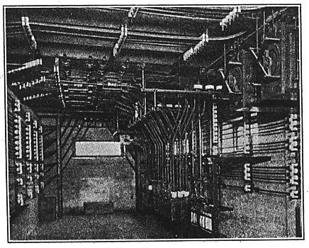
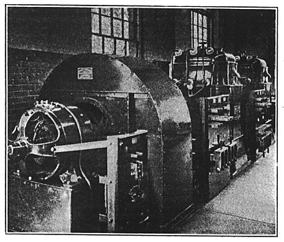
| Fig. 1. General View of the Transformer Room of Waterbury Sub-Station No. 1. |
The hydroelectric station of the New Milford Power Company at Bulls Bridge on the Housatonic River in the town of Kent, Conn., has the distinction of being the largest electric generating station using water power in New England. It possesses the largest head of water, the highest transmission voltage and the longest transmission line of any of the many hydroelectric stations in New England, while in point of capacity it exceeds any of the famous water power stations of California, save that at Electra and Colgate.
 |
| Fig. 2. Plan View Showing Lay-Out of Apparatus in Waterbury Sub-Station No. 1. |
Bulls Bridge is the site of a highway crossing over the Housatonic River, and is in that part of the valley where the river has a continuous rapid descent with steep, rocky hills close on either side. Near the bridge the valley narrows and the river has cut its way down into solid rock. Below the bridge the river makes a turn of nearly 90°, and then, after flowing nearly straight for about a mile, takes another turn that brings its general direction back to within a small angle of its former course. At a short distance above the bridge, a dam has been built across the river, and a canal starting from one end of the dam skirts the hillside for a distance of about two miles and then terminates in a forebay, where the water stands no feet above the surface of the river below the second bend just mentioned. From this forebay a steel pipe carries the water down the steep hillside to the power-house on the river bank. This type of water-power development, comprising a rather long canal, a moderate volume of water and a gradual fall in a river concentrated at a single point, so as to give a head of one to several hundred feet, is quite common in California, but has seldom been attempted in New England.
 |
| Fig. 3. Cross-Sectional Elevation of Waterbury Sub-Station No. 1. |
The steel pipe leading from the fore-bay is 13 feet in diameter, and another pipe 8 feet in diameter will subsequently be erected. This 13-ft: pipe after reaching the power-house runs along outside of its river front, and connects with seven smaller pipes that pass through the wall to the water-wheels inside. At the end of this horizontal section of the main pipe, which shrinks in diameter as pipes from the wheels are taken off, it turns into a vertical position and extends to an elevation equal to that of the crest of the main dam. The stand pipe thus formed acts to relieve any undue pressure such as might be caused by the hydraulic ram action following the shutting down of some water-wheels too quickly.
| |||
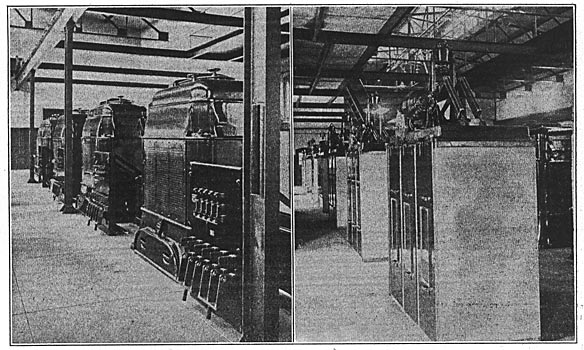
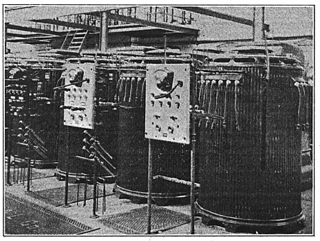
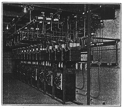
| (Left) Fig. 4. High-Tension Air Blast Transformers. (Right) Fig. 5. Motor-Driven High-Tension Oil Switches. |
The power house is built entirely of concrete and steel, the foundation being carried to solid rock. The station is formed into one main building 115 feet long by 48 feet wide with an annex in the rear and at the center 44 feet by 48 feet. In the main building are placed the wheel cases, hydraulic valves, governors, generators and exciters; while in the annex forming a part of the main building are found the switch-board, oil switches and electrical connections. In the rear of the annex and separated by a concrete partition wall a space 18 feet by 48 feet is devoted to transformers and lightning arresters.
 |
| Fig. 6. Detail of Outgoing High-Tension Line Anchorage. |
The water wheels used are of the most recent high-speed type made by the Platt Iron Works Company, of Dayton, Ohio. They are 31 inches in diameter and are placed tandem, being direct-connected to the generators and governed by Lombard water-wheel governors. Each pair of wheels has a capacity of 1750 horse-power, making a total for the six units installed of 10,500 horse-power. The three-phase generators have a capacity of 1000 kilowatts each and furnish current at 60 cycles and 1150 volts. They possess a momentary overload capacity of 50 per cent and a guaranteed overload capacity for several hours of 25 per cent. The voltage is stepped up in six oil-cooled transformers in banks of three to 33,500 volts for transmission.
| |||
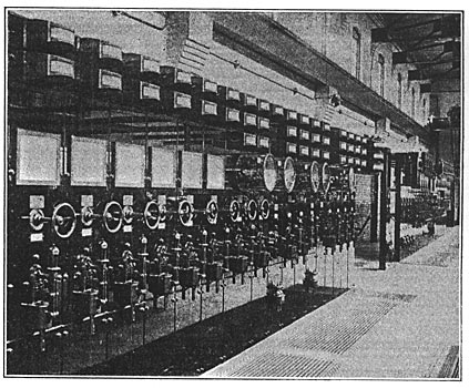
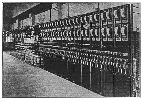
| Fig. 7. Switchboard, Waterbury Sub-Station No. 1. |
The energy from this water power plant is used on the extensive system of the Connecticut Railway & Lighting Company in Waterbury, New Britain and Cheshire. Two sub-stations are located in Waterbury from which electricity is supplied to all of the street railway lines, as well as to power and lighting circuits. The sub-station in New Britain is somewhat similar to the large sub-station in Waterbury in equipment and feeds street railway, light and power circuits. The sub-station at Cheshire is devoted exclusively to street railway work.
| |||
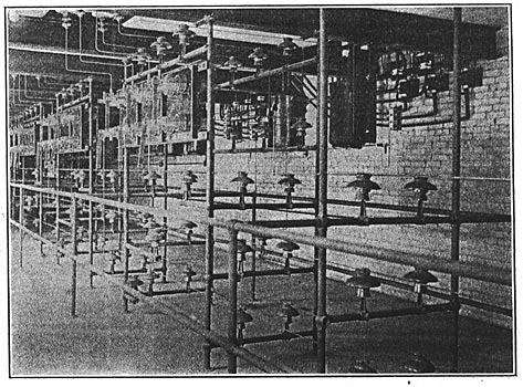
| Fig. 8. Duplicate High-Tension Bus-Bars in Basement of Sub-Station No. 1 |
Two three-phase transmission lines from Bulls Bridge run to sub-station No. 1 of the Connecticut Railway & Lighting Company at Waterbury, Conn. The Station is located on the west bank of the Naugatuck River on the outskirts of the town. Each of these three-phase circuits is made up of three bare aluminum wires having a conductivity equivalent to No. 00 copper. Energy delivered to the line at Bulls Bridge at about 33,500 volts reaches sub-station No. 1 at Waterbury over 30 miles distant with a loss ranging from 4 per cent to 7 per cent, depending on atmospheric conditions, being greatest of course during wet weather. Transformers at this station reduce the voltage to 2300 for overhead transmission through Waterbury to sub-station No. 2, situated in the center of the town. Current at a potential of 33,000 volts is also transmitted through the Waterbury sub-station, where switches are provided, to the sub-stations at New Britain and Cheshire, thus giving a transmission circuit over 40 miles long, making this the longest in New England.
| |||
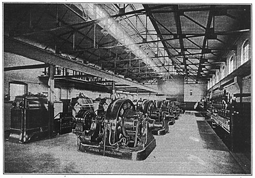
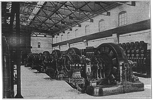
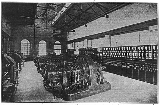
| Fig. 9. Rotary Converters in Waterbury Sub-Station No. 1, Alternating-Current Side. |
The high-tension transmission lines run across a varied country. Wooden poles are used because of the cheapness of native timber, the cross-arms being also of wood with brown porcelain insulators. The wires are placed in the form of an equilateral triangle. A telephone circuit is run on the same poles several feet below the main line, and frequent transpositions are made to nullify induction effects. The lines are carried in duplicate and on separate pole lines from Bulls Bridge to Waterbury, except on a short run, where the six wires are carried on a single pole line. The lines from Waterbury to New Britain are also in duplicate but are carried on a single pole line. The line to Cheshire is taken through a switch house outside New Britain and consists of a single pole line carrying a single three-phase circuit.
| |||
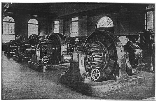
| Fig. 10. Roatary Converters From Direct-Current Side, With Booster Pedestal Switch in Foreground. |
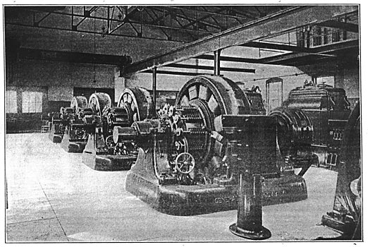
Fig. 13 is a view taken from the east bank of the Naugatuck River at Waterbury and shows the incoming and outgoing high-tension transmission lines as well as the anchorages on the station building on the opposite side of the river. Fig. 6 is a detail view of the outgoing high-tension anchorage, the incoming high-tension anchorage being almost identical. Projecting two feet two inches from the wall of the high-tension tower and running almost the entire width is a weather shield having a roof of concrete on expanded metal, with one inch slate sides and ends projecting downward a distance of 27 ins. Eighteen inches below the roof of this projection and supported on T-iron extensions is a slab of one-inch slate completely closing the shield. This slab is pierced by six porcelain floor tubes placed 26 ins. apart and in a line 11 inches from the building wall to the center of the tubes. Resting in 22-inch openings in the wall, 4 3/8 ins. from the inner side to the center of the pin are 8-inch porcelain insulators, one in line with each floor tube. Thirty-four inches below the slate floor of this shield and 12 inches from the wall are two 5 1/2 ft. pieces of hardwood 3 ins. by 4 ins. in cross-section held in position by 2 in. by 3/8 in. bar-iron brackets fastened to the wall by 5/8 in. anchor bolts. Each piece of wood has fastened to it three 9-in. insulators, one immediately below each floor tube. The insulators in the wall are separated by a 4-in. partition.
 |
| Fig. 11. Diagram of Switchboard Connections, Waterbury Sub-Station No. 1. |
After passing through the weather shield and openings in the wall the six bare wires of the transmission circuits enter single-throw double-blade knife switches which connect each wire with a bank of lightning arresters and with duplicate 33,000 volt bus-bars in the basement. Double-blade jack-knife switches tap these bus-bars and connect them with 30,000-volt motor-driven oil-break switches. From here the circuit leads to 550-kw. three-phase transformers and thence under the floorto the rotaries.
The ground area of the large sub-station in Waterbury, known as sub-Station No. 1, is 125 feet by 78 feet, and its elevation includes a high basement and main operating room or first floor above, together with a somewhat lower structure running along the side as shown by the sectional elevation in Fig. 3. From ground to coping the height of the station is 28 feet; from basement to main floor the distance is 10 feet, while the distance from the main floor to the lower cord of the steel roof trusses is 18 1/2 feet.
In structure the sub-station is of brick, concrete and steel. The walls are 12 inches thick, which is increased to 16 inches at buttresses. The basement floor is formed of a one-inch layer of cement on nine inches of concrete, and the main floor is composed of concrete arches resting on steel I-beams and all supported by the outer and by 16-in. interior walls. The floor of the adjacent room, which is used as a storage battery room, is composed of six inches of concrete covered with four and one-half inches of vitrified brick. Two towers, one on either side of the main building, as shown in the plan view, Fig. 2, 40 feet high with an interior space 13 feet square, are used for high-tension and low-tension transmission wires, the tower nearest the river being used for high-tension wires. The station is lighted by large windows along the sides and by windows in the monitor roof running along the center of the main building.
 |
| Fig. 12. Diagram of Switchboard Connections, Waterbury Sub-Station No. 1. |
The basement is divided by 16-in. interior walls into spaces for air pressure chambers, bus-bar compartments and oil switch cells. The air pressure chamber is 19 feet wide and all high-tension bus-bars are located therein. The main floor, which is 113 feet long by 50 feet wide, is swept by a ten-ton traveling crane. The I-beams on the side walls of the station are supported by brick abutments. A small gallery on the side nearest the river contains the lightning arresters and knife switches for the incoming high-tension lines. These pass directly to the basement, a narrow chamber formed by partition walls being provided for the purpose of isolating them from the main floor.
The air lock doors-for the air-pressure chamber are 2 3/4 feet by 7 feet They are made of 3/l6-in. plate riveted to a 2-in. by 2-in. by 3/16-in. L-iron frame and hinged to the wall. The handle passes through the door and catches on the curved side of the angle of a 2 1/2-in. by 2 1/2-in. by 1/4-in. L-iron frame fastened to the wall and against which the door shuts. A 3/8-in. rubber gasket is cemented to the angle of this frame around the entire surface and the pressure of the door against this gasket precludes the escape of air from the chamber. The door may be opened from either side and the bolt passing through the door has a 1/8-in rubber gasket on each end. A 4-in. hole is provided in the door so that when the outer door of the air lock chamber has been shut this hole may be uncovered and the pressure on either side of the door equalized, thus permitting the door to be opened with ease. The hole is provided with a 1/16-in. rubber gasket and is covered with a heavy iron flap hinged at the top.
| |||
| Fig. 13. Waterbury Sub-Station No. 1, Showing Incoming and Outgoing High-Tension Transmission Lines. |
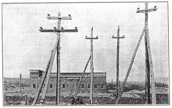
Fig 2 is a plain view of the sub-station showing the layout of the apparatus, and Figs. 9 and 10 show photographic views of the main transformer room. The equipment housed in this station consists of four 500-kw rotary converters, one 48-kw booster, four 550-kw, 33,000-volt, 00-cycle transformers with their reactance coils, eight motor-driven, high-tension oil switches, two motor-driven blowers, six single-phase transformers, six arc light transformers, a railway storage battery and an auxiliary storage battery, together with controlling switchboards. Space is provided as indicated for additional apparatus.
| |||
| Fig. 14. Oil Switches and Regulators in Basement of Sub-Station No. 1 |
The transformers are all of the air blast type, the primary and secondary voltages of the 550-kw. units being 33,000 and 430, respectively. The primary and secondary voltages of the 500-kw., single-phase transformers are 33,000 and 2,300, respectively. The air pressure maintained in the chamber beneath the transformers is 5/8 oz. Two Buffalo Forge Company's fans, each direct-driven by a 350-volt, 60-cycle, 7 1/2-h.p. induction motor, supply the air for the air pressure chamber. These units are located just beyond and in line with the large transformers about the center of the room and beside each induction motor is a switch panel carrying the necessary apparatus for throwing the motor into circuit.
The rotaries, of which there are four installed, are 60-cycle machines having twelve poles and running at 600 r.p.m. They each deliver 833 amperes of direct current at a potential of 600 volts. Each rotary is started from standstill by means of a 50-h.p. induction motor mounted upon the rotary converter shaft, and when the armature is thus brought up to synchronous speed connection is made to the alternating-current mains. Switches are provided for starting the rotaries as direct-current motors from the commutator end, but this method of starting is seldom it ever used. The current from the rotaries is used entirely for railway purposes, the maximum load of which is 2500 amperes, which comes on at noon.
| |||
| Fig. 15. Series Arc Light Transformers in Waterbury Sub-Station No. 1 |
The high-tension transformer oil switches have a capacity of 200 amperes at 30,000 volts. These switches are operated by direct-current series motors taking 11 amperes at no volts and running at 2,800 r.p.m. The operation of the oil switch may be accomplished by a small single-pole, double-throw, hand-controlling switch mounted on a panel of the main switch-board. Red and green lights indicate whether the oil switch is closed or open. Six breaks are provided in the triple-pole switch, each break taking place in a separate oil receptacle and in addition each phase is enclosed in a fireproof compartment. The cells are constructed of brick, with top and bottom slabs of slate. The switches installed are all automatic in operation, a relay operated by current transformers closing the direct-current operating motor circuit. Fig. 5 shows the line of large oil switches.
| |||
| Fig. 16. General View of the Interior of Waterbury Sub-Station No. 2 |
The six 500-kw. transformers are arranged in banks of three, and the 2.300-volt secondary current chained from them is transmitted over two separate trunk lines of No. 000 copper to sub-station No. 2 in the center of the town. The six constant-current transformers are used for series arc lighting; single-phase arc lighting circuits running to Naugatuck, North Willow and Highland Park, Waterville, East Waterbury, North Waterbury and Forest Park, Watertown, South Waterbury and Platt's Mill. The line to Watertown has a straight run of six miles before distribution is made. A three-phase feeder line also runs to Naugatuck, where it is split up into three single-phase circuits.
| |||
| Fig. 17. Nearer View of Rotary Converters From the Direct-Current End. |
 |
| Fig. 18. Plan View Showing Lay-Out of Apparatus in Waterbury Sub-Station No. 2. |
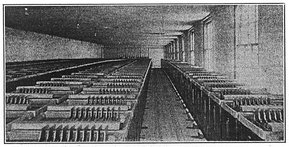
The storage battery used on the railway circuits consists of 288 type G-27 cells. The voltage is 600 and the rate of discharge is 720 amperes for one hour. The auxiliary storage battery consists of 55 type D-9 cells and the voltage is 110, with a discharge rate of 10 amperes for eight hours. This battery is used to supply current to the motors of the oil switches and pilots. The indescent [sic] incandescent lamps are wired five in series with a 2,300/500 volt transformer to a supply circuit. In case of shut down at New Milford a throw-over switch connects these circuits with the main storage battery so that the station will at no time be without light. The alternating-current enclosed arc lights with which the station is bountifully provided are fed from a separate 104-volt transformer circuit in the station.
| |||
| Fig. 19. 2300-Volt Air-Blast Transformers and Direct-Current, Motor-Driven Blower. |
A view of the switchboard is shown by Fig. 7 and a diagram of its connections cut in two for convenience of printing, is shown in Figs. 11 and 12. The board is made of black enameled slate and contains 40 panels, distributed as follows: Five double-circuit railway feeder panels, five single-circuit feeder panels, three battery-booster panels, four direct-current rotary panels, four three-phase power, panels, two three-phase trunk line panels to sub-station No. 2, one totalizing panel for arc light circuits, one three-phase panel, six single-phase lighting panels and three sectioning panels. The circuit-breakers, ammeters, rheostats, hand-wheels, switches, etc., are of uniform design and occupy the same position on all panels thus giving a symmetrical appearance to the switchboard. The circuit-breakers on the railway feeder panels are equipped with a tell-tale device which completes the circuit of an alarm bell when the breaker opens. The device is automatically reset when the breaker is closed again. The circuit-breakers on the converter panels in addition to having this tell-tale device have low-voltage release coils which trip the breakers when the voltage drops below a certain point. The low-voltage release coil is used in connection with a centrifugal speed limiting switch mounted on the shaft of the rotary, and which short-circuits the low-voltage release coil and opens the circuit-breaker in case the speed exceeds the normal.
| |||
| Fig. 20. Oil Switches, Regulators, Etc., in Waterbury Sub-Station No. 2 |
The panels controlling the 2,300-volt three-phase and single-phase circuits are grouped together, but the bus-bars are divided into four sections by three section switches, thereby giving great flexibility in the matter of connections. The power circuits, trunk-line circuits, arc-light circuits and incandescent circuits are all metered separately. Oil switches are used on these panels, the operating mechanism being controlled by the switch through rods passing through the floor. Fig. 14 shows the oil cells and regulators in the basement beneath the switchboard. The oil switches are electrically tripped on overload, with the exception of the sectioning switches which are not equipped with the electrical releasing device. The device is shown clearly beneath the switches in the engraving of the switchbooard. Fig. 7. Practically all of the wiring is run in the basement, where ample room is provided in which to work. No wires carrying high-tension current are brought directly to the switch-board. 450 series arc lamps and about 30,000 incandescent lamps are fed from this station.
Sub-station No. 2 is somewhat smaller in size and equipment than the sub-station just described and covers an area 35 feet by 70 feet. A plan view of the station and its equipment is shown by Fig. 18, and Figs. 16 and 17 are photographic views of the rotaries. The incoming trunk lines from Sub-station No. 1 may be seen in the background of Fig. 16. These pass directly to the bus-bars and switches in the basement.
 |
| Fig. 21. Diagram of Switchboard Connections, Waterbury Sub-Station No. 2 |
The equipment of the station consists of four 300-kw. rotary converters, with their starting motors, four 300-kw., three-phase transformers with potential regulators and two motor-driven fans together with a switchboard running along the side almost the entire length of the station. That portion of the basement beneath the transformers is laid out as an air-pressure chamber, while that portion below the switchboard contains the oil switches, bus-bars, regulators, etc., as shown in Fig. 20.
The converters are oo-cycle machines, running at 600 r.p.m. and delivering direct-current at 275 volts. They are brought up to speed by 30-h.p. induction motors, but may be started from the direct-current side also. Space is provided for additional machines. The transformers have a primary voltage of 2,300 volts and secondary voltage of 188 volts. The fans are of the Buffalo Forge Company's make and are driven by a 5-h.p., direct-current motor at 400 r.p.m. The air pressure maintained is 3/8 oz. Four I-T-R potential regulators are installed, each being operated by a 1/4-h.p. induction motor. These regulate the alternating-current voltage delivered to the transformers. Almost all the regulation is obtained in this way, very little being possible from the direct-current end. The panel in front of each regulator contains a three-point, double-throw starting switch, a single-throw neutral switch and two double-pole, double-throw, alternating-current running switches.
| |||
| Fig. 22. Switchboard, Waterbury Sub-Station No. 2 |
The switchboard is shown in Fig. 22 and a diagram of its connections is shown by Fig. 21. It is equipped with high and low voltage bus-bars and the switches are double-throw, so that when thrown up they connect with the high voltage bus, and when thrown down they connect to the low-voltage bus. The high-voltage bus-bars are, however, not at present in use. The board contains 12 feeder panels, having 48 feeder switches, one-half of which are only at present connected. The station is devoted entirely to power and lighting work on the Edison three-wire system. The territory fed by the station is about one square mile, the station being at about the center of the load. Overhead wires are at present used, but by the time this article appears, work will be commenced on an underground conduit system. The commercial multiple-arc lamps connected number about 900 and the incandescent lamps number over 20,000. The entire electrical equipment of the Connecticut Railway & Lighting Company's sub-stations at Waterbury, including series and multiple arc lamps, as well as the electrical equipment of the New Milford Company's hydroelectric station at Bulls Bridge was supplied by the General Electric Company.
| |||
| Fig. 23. Storage-Batteries in Waterbury Sub-Station No. 1 |
The load in Waterbury was previously carried by a steam-driven central station on Bank Street bordering on the Naugatuck River. This station is now maintained as a reserve in case of any accident to the transmission plant at Bulls Bridge; but this is so well guarded against that a failure of supply is almost impossible, and :it will be only a matter of time when the old steam station will be dismantled. The superintendent of the Waterbury station is Mr. D. B. Neth, to whom we are indebted for many courtesies extended in the preparation of this article.
