[Trade Journal]
Publication: Electrical Review
New York, NY, United States
vol. 13, no. 9, p. 1;1-4, col. 1-2;1-4
THE WESTINGHOUSE SYSTEM ELECTRICAL DISTRIBUTION FOR LIGHT AND POWER.
Owing to the crowded condition of our columns this week we are compelled to issue a supplement in order to give our readers a full exposition of this now splendidly complete system.
As the alternating current motor is perhaps the most interesting of the details, we present it first, illustrating it on page 1 of our regular edition.
The alternating current motor consists of a series of field magnets, wound with two sets of coils, the ends of which are connected binding posts conveniently located for attachment to the supply circuit. These binding post form the only connection with the current, which current is taken from the regular lighting circuits, with the addition of a single return wire. This return wire makes it possible to send two alternating currents through the field of the motor at the same time, the pulsations of the two currents being similar but not simultaneous. The resultant of these two currents is that a rapidly rotating polarity is given to the field, corresponding in period to that of the current producing it.
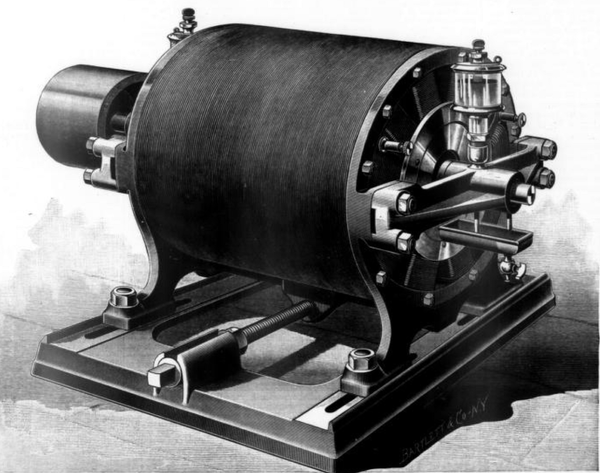 |
| The Westinghouse Electric Motor Tesla Patent. |
The armature is in appearance similar to the ordinary Siemens drum armature, without the commuter. The winding is, however, much simpler, and consists of a few turns of comparatively small wire, the ends of which, instead of being carried out to a collecting ring, or any other form of sliding contact, are soldered together, forming a closed circuit having no connection with the energizing current. The alternating currents in the field induce secondary currents in the armature, and by the attraction between these and the revolving polarity of the field, rotation is produced, the rate of rotation corresponding very nearly with that of the field.
When no work is being done by the motor, the synchronism is exact, or nearly
(Continued in Supplement.)
SUPPLEMENT
THE WESTINGHOUSE SYSTEM
Electrical Distribution for Light and Power. (Continued from page 1, Regular Edition.)
so, and very little passes either through the armature or field, but as load is put on and the work increases, the armature tends to lag slightly, causing the passage of more current in proportion to the work done. The reaction between the armature and the field is similar to that between the primary and secondary coils of a converter, and the increase of load on the motor causes increased supply of current in a manner exactly as takes place when lamps are added to the secondary-circuit of a converter. The addition of the return wire for the motor circuit can be made easily so as to adapt existing lighting circuits to motor work, and the armature of the dynamo used for driving motors is equally available for lighting purposes.
By an ingenious adaptation of the converter principle, this motor may be regulated in speed and reversed in its direction of motion without the use of resistance coil. The method of operation is exactly similar to the link reversing gear of a locomotive. The extreme position of the reversing lever in one direction corresponds to full speed ahead, from which it can be graduated through every shade of intermediate speed to the reversing point, and from that on to full speed backwards. This is more readily accomplished owing to the absence of brushes, since there can be no sparking or wear due to the passage of current under any circumstances. Not attention need be given to the motor beyond the filling and cleaning of the oil cups.
| |||
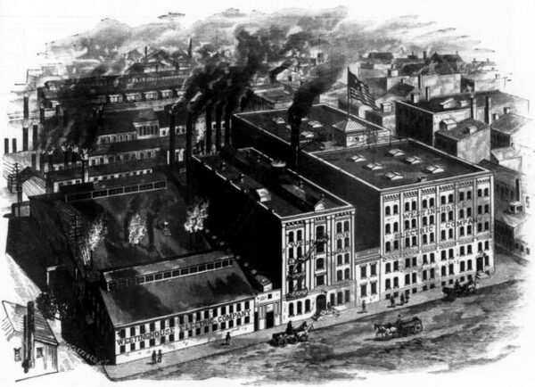
| The Factories of the Westinghouse Electric Company, Pittsburgh, Pa. |
The alternating motor is more compact than the direct current motor, and lighter in proportion to the power delivered. It can be served either through a converter or directly from the primary circuits. The connections may be so protected that no inconvenience or danger can possibly result from direct connection to high tension service should such become desirable. As there are no sliding contacts, and the binding posts need never be touched or even exposed in any way, the use of a high tension current becomes possible. The extreme simplicity of the winding and general construction of this motor makes it very unlikely to get out of repair. The insulation of the armature is of no importance, since the current traversing it is never but a few volts and often less than one volt, regardless of the voltage of the supplying circuits. Absolutely no electrical knowledge is required in its operation, and the connections to the circuit in erecting are so simple that any one of ordinary intelligence can make them with ease and certainty. The alternating current motor is therefore thoroughly practical for manufacturing, commercial and domestic use in the hands of servants.
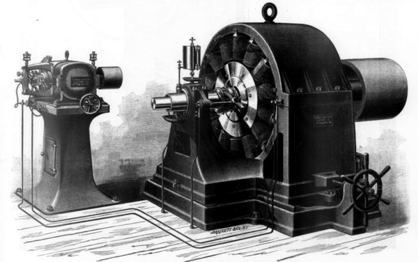 |
| Westinghouse Dynamoe With Exciter. |
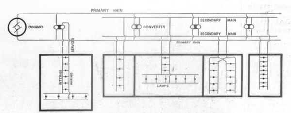 |
| Diagram Illustrating Relation of Converters to Dynamo and Lamps. |
| |||
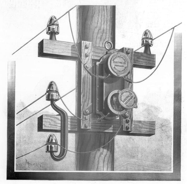
| Converter With Direct Service Wires. |
| |||
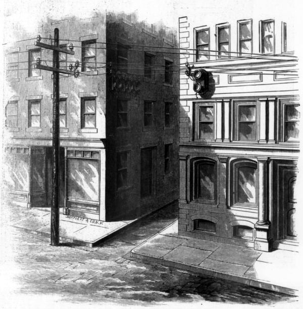
| Converters on Building. |
 |
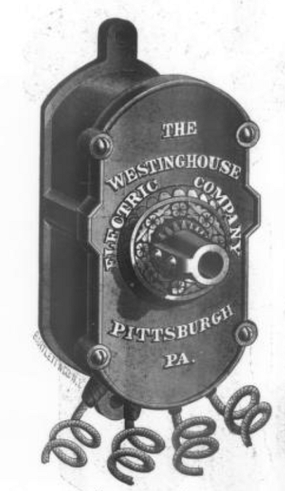
| Lightning Arrester. |
 |
| Compensator. |
Our readers are familiar with the construction and details of the salient features of the system, such as the alternating current dynamo exciter and the converter, and we herein illustrate these various parts in their latest development, without further detail or description. Every feature has been designed with skill indeed
The generators are made in four sizes of a capacity respectively of 500, 750, 1,500 and 3,000 lamps of 16 candles each. The converters are also in four sizes, 10, 20, 30 and 40 amperes in the secondary or low tension circuit, enough for 14, 28, 42 and 56 lamps. The general aim is to do as much distributing as possible with the primary and make the secondary short. The converters are placed on the line poles or on the outer wall of the building, the latter preferred, for very long distance work, a converter at the station raises the standard E.M.F. to 2,000 volts, and the ordinary line converters are connected at the consumption points, two and two, their primaries in series and secondaries in multiple. The compensator is a most ingenious satellite of the alternator system, serving the purpose of the extra pressure-wire of direct current systems, to enable the dynamo tender to preserve a constant drop of potential. The ammeters connected through the switchboard by short-circuiting plugs, show the volume of current on the mains. The ground detector is an interesting example of careful designing, and is very prompt and reliable. A standard voltmeter forms a very desirable part of every station equipment, and is so constructed as to be constant in its readings. By it the service voltmeters are calibrated.
| |||
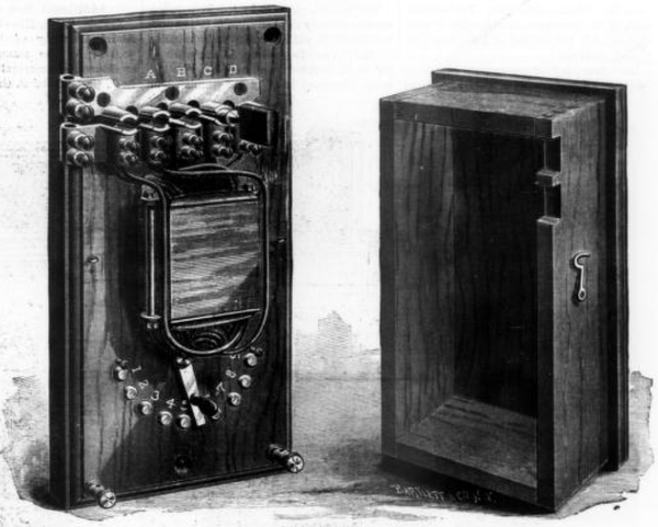
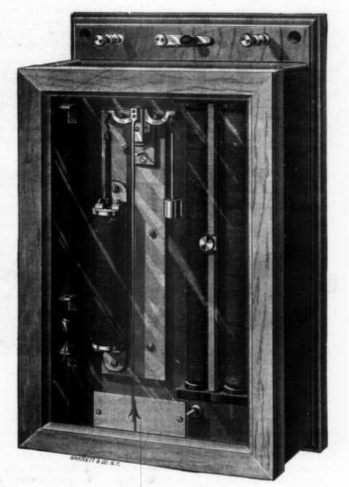
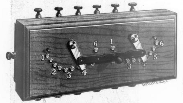
| The Westinghouse Switchboard. |
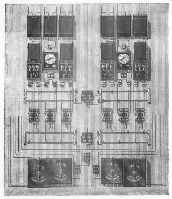
The station switchboard is a beautiful sample of compactness. The figure shows one arranged for two exciters, two dynamos and four lines. Two exciter rheostats with changing switches have an obvious use, as also two dynamo field rheostats with coupling switch between. Four pairs of trunk wires with two multiple-arcing switches, and six changing switches render any service connection possible in an instant. Four voltmeters and compensators are arranged for instant connection with the respective lines, and two ammeters, by means of the changing switches can be used rapidly, and plugged out instantly. All the devices are guarded by safety catches.
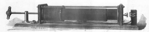 |
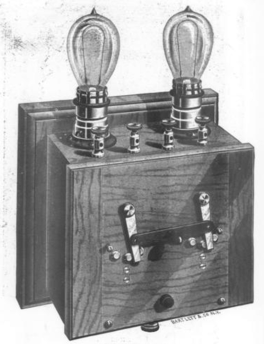
| Stage Regulator. |
The stage regulator admirably illustrates the readiness with which the principles of induction lend themselves to the various purposes of hand regulation and control of current. The simple movement, in or-out, of the rod, raises or lowers the brilliancy of the lamps as required. The house regulator. Serves a similar purpose, but is based on somewhat different principles. The convolutions of the converter are adjustable in their number and the amount of induction thus readily governed.
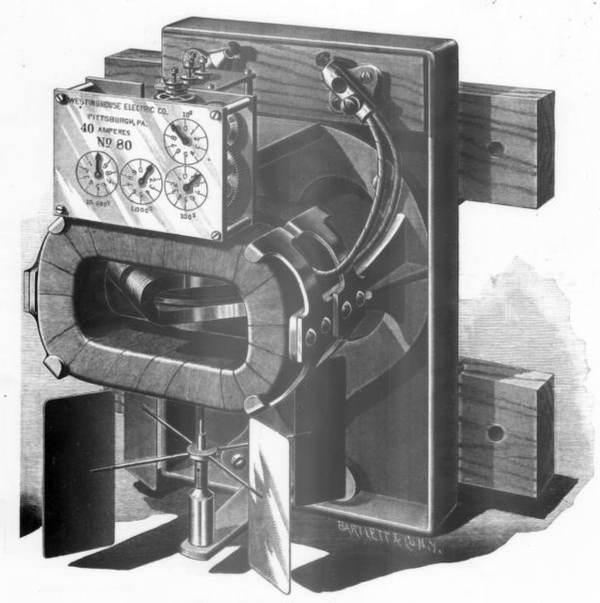 |
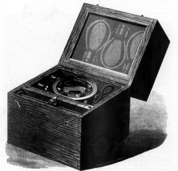
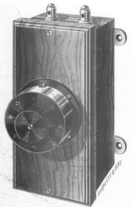
| Alternating Current Meter Shallenberger Patent. |
The alternation current meter is especially deserving of praise. By it a shaft is rotated at a speed proportional to the square of the current, but this is offset to a simple proportion by a fan-wheel, and a certain speed of revolution counts off the ampere hours regularly. The consumer can, therefore, check his own meter readily.
The system, at least in the keen refinements necessary to fit the means to the end, and largely in the conception and designing of the devices themselves, is the work of Mr. O. B. Shallenberger, and the Westinghouse Company is to be congratulated on the possession of an electrician who, while yet young and vigorous, has such judgment and capacity.
 |
| Ammeter. |
 |
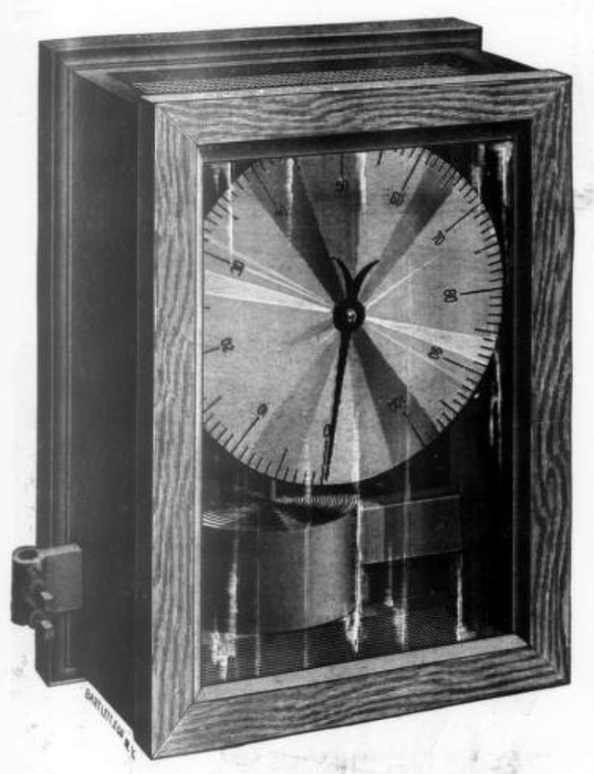
| Standard Volt Meter. |
 |
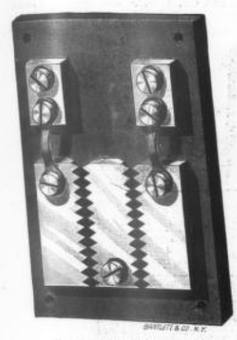
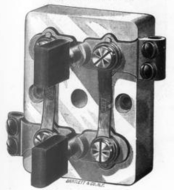
| Short Circuiting Plug. |
 |
| Safety Catch Holder. |
 |
| Portable Volt Meter. |
 |
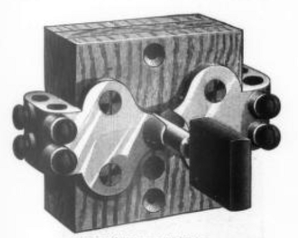
| Ground Detector Switch. |
 |
| Ground Detector. |
 |
| The House Regulator. |
 |
| Street Lamp Coil. |
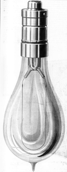 |
| Special Lamp50 and 75 Candle Power. |
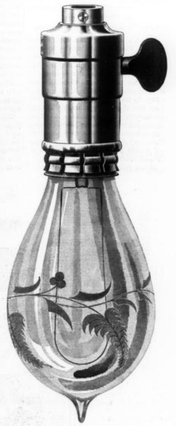 |
| Engraved Lamp. |
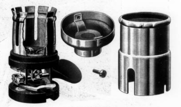 |
| Details of Socket. |
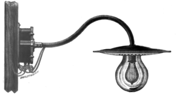 |
| Combined Fixture and Coil. |
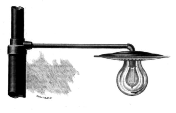 |
| Street Lamp Fixture. |
