[Trade Journal]
Publication: Western Electrician
Chicago, IL, United States
vol. 36, no. 17, p. 321-324, col. 1-3
Electricity as Used in the Operation of Lead and Zinc Mines Near Joplin, Mo.
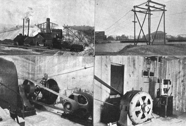
The Joplin mining district, the lead and zinc fields of the state of Missouri, extends from Galena, Cherokee County, Kan, east through Jasper County, Mo., to Carthage, and from South Joplin, Mo., north as far as Alba and Neck City, comprising in area about 150 square miles. The mining industry in this section dates back to about 1878, during which time it has been continually increasing in volume, until the present output of zinc and lead ores amounts to slightly over $7,000,000 a year, this consisting of nearly 200,000 tons of zinc ore and perhaps 25,000 tons of lead ore. At first the lead only was mined, the ore being found very close to the surface of the ground. Later, when the surface ore was exhausted and it was necessary to go deeper for the lead, quantities of zinc ore were found. Since that time the importance of the zinc industry has rapidly increased until now it is far in excess of the lead industry. Fig. 1 is a view of one of the better class of ore mills; and an idea of the number of these mills that have sprung up in parts of the district may also be gained from the picture.
| |||
| Fig. 1. Type of Better Class of Ore Mills. Fig. 2. Dam, Power House and Long Span Across Shoal Creek. Fig. 3. One of the Generators Showing Connection to Turbine Shaft. Fig. 4. Typical Mill Installation. Electricity As Used in the Operation of Lead and Zinc Mines Near Joplin, Mo. |
Zinc ore is found in pockets, and the amount of ore upon any mining claim cannot accurately he determined by prospecting. This makes the life of any particular shaft very uncertain, but the average may he placed at three years. Some pockets are worked out within a few months, while others are worked for a period of five or six years before being exhausted.
This characteristic of the zinc fields makes it necessary to change the location of the mills at frequent intervals, and as a result of this the machinery is installed at the least possible expense and all installations are of a very temporary nature. One direct result is a very low efficiency in operation. Steam plants in comparatively small units, and very cheaply installed, do not give a very high mechanical efficiency, and result in a high cost of power to the mine operators. This position was recognized by the capitalists interested in certain Joplin mines, and as the result of their investigations it was decided that the waterpower along Spring River should be investigated with a view to utilizing this power throughout the mining district. For this purpose the Spring River Power Company of Joplin, Mo., was organized. The company is composed of Chicago men. Mr. Francis W. Farwell is president, Mr. Jamot Brown, vice president, and Mr. Samuel Brown, Jr., secretary and treasurer. The Arnold Company of Chicago was commissioned to prepare complete plans and specifications for the proposed development, and later was awarded the contract for the entire construction.
Following these plans a hydro-electric plant has been located at Lowell, Kan., at the confluence of Spring River and Shoal Creek. At this point a darn was constructed and the necessary turbines and generators installed, as well as the step-up transformers and the necessary switching apparatus. From this point a transmission line leads through the zinc district, by the cities of Galena, Joplin and Webb Cityin all about 30 miles. Four sub-stations were constructed, and from these secondary lines lead out to the mills to be supplied with electric power. For the transmission line a voltage of 33,000 was chosen, while for the secondary distribution 2,300 volts is used. In taking tip the description of the property somewhat in detail, it may be well to begin with the work at Lowell and take up the various parts of the property in sequence.
THE DAM AND POWER PLANT.
The dam (Fig. 2) is constructed entirely of concrete resting upon solid rock in and below the embodies in its length two turbine rooms, each 99 feet long, between which is located the generator room, 45 feet long by 30 feet wide, which is plainly shown in Fig. 2 . At the north end of the central part of the structure the controlling gates located, occupying a distance of 95 feet in the length of the dam. At this point are installed five Taintor gates, and directly below the gates, on the downstream side of the dam, are the aprons, affording a spillway for the water allowed to go through the gates. From the north end of the dam a core wall and an earth embankment extend northwesterly for a distance of about 800 feet. At this point the embankment runs into the road leading from Lowell to Varck. The grade of this road has been raised for a distance of about three quarters of a mile beyond the end of the core wall. At a point along this road, about half a mile from the dam, sluice gates are installed, which makes it possible to divert a part of the river's flow during flood time. The water so diverted flows into Spring River about three-quarters of a mile below.
The layout of the dam and power house is somewhat unique, the generator and turbine rooms being a part of the dam. The normal elevation of the water in the tailrace will be about 113 feet. The floor of the turbine room is at an elevation of 121 feet, and from this floor the draft tubes under the turbines project downward into discharge tunnels built in solid masonry in the lower part of the dam. The normal elevation of the headwater is 141 feet, thus giving an available head of 28 feet. The turbines are installed on the floor of the turbine room and are practically situated on the river bed just above the dam. This method of entirely doing away with the headrace is very advantageous, as there is no question of difficulty arising from any currents which often are found in the headrace of ordinary construction. Fig, 5 is a view showing a plan and sectional elevations of the plant.
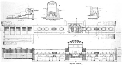 |
| Fig. 5 Plan and Sectional Elevations of Electric Power Plant for the Operation of Lead and Zinc Mixes. |
In each turbine room are installed four pairs of horizontal turbines, all mounted on one shaft. The shaft extends through bulkheads into the generator room, where it is directly connected to the generator, as seen in Fig. 3. This exceedingly simple construction is the most desirable, as in the operation of the plant there is absolutely nothing necessary but to attend to the bearings.
In front of the turbine room is installed a grid bar rack, supported by steel columns placed five feet apart. Provision is made for mounting sliding gates between these columns in case it is desirable to shut the headwater off from the turbine room in order to make repairs on wheels.
The roof of the turbine room consists of heavy planking laid over the steel beams connecting the top of the columns with the dam proper, which forms the back of the turbine room. This construction is seen in section CC, Fig. 5. Section BB is taken through the generator room and shows the relative location of the generators, exciters and switchboard, Section AA shows the construction of the Taintor gates. The axes of these gates consist of two 15-inch 42-pound I-beams, securely riveted together with steel plates and the necessary angle plates for attaching the wooden framing, The radius of these gates is about 13-1/2 feet. As plainly indicated in the cut, they are designed to allow the water to pass through underneath the gate. By means of the controlling gates, the headwater can be kept at any desired height. The gates are designed to take care of the excess water at all ordinary times. In case of extreme high water, the overflow is to be taken care of by the special cut-off referred to in a preceding paragraph.
The turbines were furnished by James Leffel & Co. of Springfield, Ohio. There are two units, each consisting of four pairs of the latest improved 42-1/2-inch center-discharge horizontal turbines connected in tandem on horizontal shafts. The turbines are designed to run at from 180 to 200 revolutions a minute and will develop 80 per cent. of the theoretical efficiency under a 24-foot working head. Each pair of turbines is mounted on heavy base plates, which in turn are mounted on heavy steel beams, forming the turbine-room floor. Each two pairs of turbines are provided with one gate shaft, and the end of each gate shaft is provided with couplings for direct connection to a Lombard governor. The installation, as noted above, contemplates receiving the water in an open flume, thoroughly protected by racks, and discharging the water through central-draft tubes set vertically below each pair of wheels. The lower end of these tubes is to be at all times submerged at a depth of from six to 12 inches. The tailwater will at all times show a depth of from 10 to 12 feet in the channel below the bottom of the draft tubes. The turbines, under a working head of 24 feet, will develop 2,800 horsepower at about seven-eighths of full gateage. This gives a total capacity of 2,800 horsepower in each unit, or 5,600 horsepower in all.
The electrical equipment in the generator room is very simple. To the end of each turbine shaft is directly coupled the shaft of a 1,500-kilowatt three-phase 25-cycle 2,300-volt alternating-current generator, designed to operate at 187-1/2 revolutions a minute. One only of these machines is shown in Fig. 3. A 55-kilowatt 125-volt direct-current exciter is directly belted to each turbine shaft. Each exciter is of sufficient capacity to provide current for both generators, and at the same time supply the necessary current for lighting and small motors about the plant. These two generators and two exciters, together with the switchboard, constitute all the electrical apparatus installed in the generator room. The step-up transformers and high-tension switches are installed in the transformer house, located on the hank of the river about so feet south of the south end of the dam, and indicated in Fig. 2. As seen from the plan, the switchboard is located on the upstream side of the generator room about 4-1/4 feet from the wall.
The generator-field rheostats are installed in pits underneath and behind the switchboard. The current and potential transformers used in connection with the 2,300-volt generators are installed in a pit of ample size underneath the generators. This pit also makes it possible to make any necessary repairs underneath the large generators. In the generator room is installed a 15-ton hand-power traveling crane, which greatly facilitates any small repairs that may be necessary. The crane was furnished by the Whiting Foundry Equipment Company of Harvey, Ill. All the electrical apparatus in the generator room and transformer house was furnished by the General Electric Company.
Current generated in the generator room at 2,300 volts is taken directly through a three-wire paper-insulated lead-encased cable to the transformer house and led directly to the low-tension side of the transformers. From the high-tension side of the transformers the current is led through oil switches and single-pole disconnecting switches to the high-tension bus bars, and from the bus bars through single-pole disconnecting switches and oil switches to the line. The line is protected by lightning arresters. The high-tension switches installed in the transformer house are operated from the switchboard in the generator room by means of the General Electric standard system of remote control. Leads are also brought back from the current transformers installed in the line circuits to the switchboard, where they are connected with ammeters on the line panel.
The switchboard consists at present of five panels. There are two exciter panels, on which are mounted ammeter, voltmeter, exciter, rheostat and main switch. There are also two generator panels on which are mounted ammeter, voltmeter and indicating and recording wattmeters for the 1,300 kilowatt alternators; also the remote-control switch for operating the oil switch installed in the transformer house.
Electrical connections between the generator room and transformer house are all paper-covered, lead-encased cable laid in tile ducts of ample size. For each generator there is a three-wire 600,000-circular-mil cable, each laid in its own tile duct. Other ducts of ample size are pro-vided. In these are laid the two-wire cables used for switch control and for instrument leads. There is as well a 125-volt line leading from the main switchboard bus bars to distributing panels in the transformer house for furnishing light and power to small motors. In the transformer house are installed the six 500-kilowatt, 2,300-33,000-volt water - cooled transformers, the necessary oil switches, the high-tension bus bars, the lightning arresters and the necessary current and potential transformers. The building is constructed of hollow tile and is approximately 41 feet long by 31 feet wide. It is shown at the left in Fig. 2. The 2,300-volt cables end in the ordinary discharge bells, located on the side of the transformer room. The cables lead directly to the low-tension delta connection for the low-tension side of the trans-former. The high-tension delta is installed directly above the transformers. All the wire connections are made of No. 2 bare copper wire, supported on a Locke insulator. The high-tension lines pass through Locke wall insulators into another part of the transformer house and pass directly to the oil switches. The oil switches are supported on the floor of the second story, the floor being constructed of concrete and steel. The bus-bar compartment is located directly beneath the switches and is built up of the hollow tile used in the building construction. Between the high-tension bus bars and the switches are installed single-blade disconnecting switches.
For the outgoing line, the leads pass from the high-tension bus through the disconnecting switch to the oil switch, thence along the ceiling to the opposite side of the room, then directly up along the wall back of the lightning arresters to the double-pole disconnecting switch near the high-tension entrance.
The entrance to the building is built up of slate panels mounted on strap-iron supports. The high-tension wire passes directly through an opening in the wall of the transformer house into this wiring compartment and downward through a porcelain insulator to a standard line insulator mounted on a bracket on the outside of the building wall. This insulator serves to take up all strain at the end of the line. The impedance coils used in connection with the lightning arresters are formed by winding the conductor in the form of a spiral about six inches in diameter with one-half-inch pitch, and placing these coils along the wall directly back of the arrester. This gives a very compact and simple layout. At present only three oil switches are installedone for each generator-transformer unit and one for the line. Space has been provided in the design of the building for the installation of two more such switches when additional transmission lines are built. Space is also provided for the necessary future lightning arresters.
Circulating water for the transformers is drawn in from the river above the dam by means of a small centrifugal pump direct connected to a 125-volt two-horsepower motor, and after passing through the transformers is discharged through a pipe, the end of which is submerged below the tail-water. The difference in head tinder normal conditions is sufficient to maintain the necessary circulation, the system acting as a simple syphon; but, in order to start the syphon in operation and assure positive operation, the circulating pump has been installed.
TRANSMISSION LINE AND SUB-STATIONS.
The transmission line consists of three No. 4 hare copper wires supported on Locke No. 311 insulators. The wires are arranged in the form of a delta, the top insulator being attached by means of a ridge iron to the top of the pole. The two lower insulators are supported on a 3-1/4 by 4-1/4-inch five-foot cross-arm. All insulator pins are provided with porcelain bases. The distance between wires is 44 inches. A ground wire, consisting of No. 6 soft-drawn steel, is installed on the side of the pole about two feet below the bottom of the cross-arm. This wire is attached to the pole by means of a three-eighths by three-inch lag screw and washers and is carried from pole to pole parallel to the transmission-line wires. At every fourth pole a ground connection leads from the ground wire to the ground and is buried below the bottom of the pole. These precautions have been taken on account of the fact that the district through which the transmission line runs is subject to very severe electrical storms during a good portion of the year. It is hoped that the carrying of the ground wire so near to the transmission line, together with its frequent grounding, may materially lessen the difficulties in the operation of the system. The standard poles are 35 feet long with seven-inch top, set six feet in the ground, and this brings the lower wire of the transmission line to about 26 feet above the ground, while the ground wire is about 23 feet above the ground. Upon leaving the transformer house the line crosses the river by a single long span, as shown in Fig. 3.
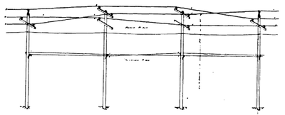 |
| Fig. 6. Method of Transposing Transmission Lines With Double Cross-Arms. |
In transposing the transmission line, a partial revolution is made about once every mile, the number of transpositions being so chosen as to make a complete turn in the delta in each section of the line, that part of the line between the power house and sub-station, or between any two substations being considered as a section, the sections being from two to three miles long. Fig. 6 shows the method of transposing with double cross-arms, one-third of a revolution being shown. The telephone line is installed about six feet below the ground wire, this line being transposed every second pole. This is accomplished by using a transposition insulator on every other pole and two telephone insulators on the intermediate poles. It is found that this frequent transposition very materially decreases all difficulties, due to induction, arising from the high-tension line.
| |||
| Fig. 7. Transmission Wires Crossing Railroad Tracks. |
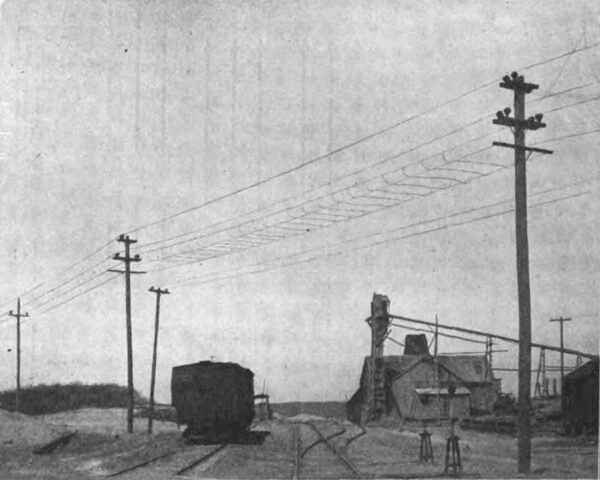
Wherever the line crosses the main tracks of steam roads, special cradles are installed, as shown in Fig. 7, composed of No. 4 steel wire, so designed as to prevent any broken transmission wire from reaching the ground. These cradles are very thoroughly grounded, which will result in tripping the automatic oil switch, thus throwing the broken wire out of commission in case any break should occur in the line. Similar protection has been provided in case it is necessary for the transmission line to cross other transmission lines or telegraph lines. In the latter case, however, wherever it is possible, as in the case of the transmission line crossing the telephone line at right angles, two poles have been set as close as possible on either side of the telephone line, making it impossible for any broken transmission wire to fall on the telephone line.
| |||
| Fig. 8. Sub-Station No. I of Joplin Power - Transmission Plant. |
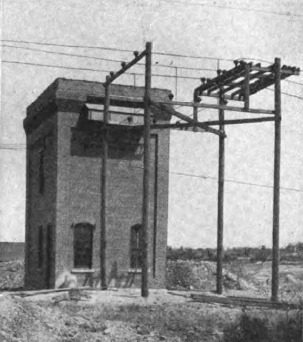
At present four sub-stations are being installedone near Galena, one near Joplin, one southwest of Webb City in the Prosperity mining district, and one north of Webb City in the Oronogo mining district. At each substation there is installed in the main transmission line a horn switch of special design, the arrangement being such that the transmission line on the side furthest from the generating plant may be cut off. This provision is made so that, in case of difficulty on the line, no sub-station between the fault and the generating plant need be permanently put out of service. By opening this switch repairs can be made on the line, while all sub-stations nearer the generating plant can be kept in operation. Between Joplin and Webb City there is a branch in the main transmission lineone branch leading to the Prosperity sub-station and the other branch leading to the Oronogo sub-station. At this junction point two air-brake switches are installed, thus making it possible to cut either end of the line off from the main line leading to the dam.
Sub-station No. 1, Fig. 8, is located near Galena, while that known as sub-station No. 2 is located near Joplin. These two sub-stations are each built of brick and are about 18 feet square (outside measurement) by about 30 feet high. The line entrance is in every respect similar to that used in the construction of the transformer house at Lowell, and likewise similar lightning arresters, designed for 30,000 volts, are connected to the line just inside of the entrance. Three single-pole oil switches, provided with suitable mechanism for hand operation, are installed on the second floor of the sub-stations.
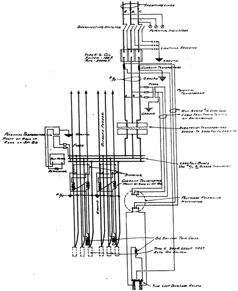 |
| Fig. 9. Wiring Diagram of Typical Sub-Station of Joplin Power-Transmission Plant. |
The operating mechanism is connected to the switchboard, which is installed on the lower floor in front of the transformers. The high-tension wires coming from the oil switches pass directly to the delta, and thence to the transformers located on the lower floor. Three 250-kilowatt 25-cycle 30,000-2,300-volt water-cooled transformers are installed in each sub-station. The switchboard consists of one 30,000-volt panel, controlling the incoming line, and two 2,300-volt panels, controlling the outgoing secondary lines. From the 2,300-volt secondaries of the transformers, leads arc taken directly to the low-tension delta, which is carried on bus-bar racks mounted on the front of the transformers. From the delta, lead-covered cable leads directly to the floor, and under the floor to the bus bars on the switchboard. From the feeder-line switches the cables are carried in conduits under the floor, thence up the wall and out through porcelain insulating tubes to the secondary distributing line. Fig. 9 is a wiring diagram typical of the four sub-stations and explaining the general arrangement of the apparatus.
The design of the sub-stations is made as simple as possible, there being provided only one high-tension switch for disconnecting the sub-station from the line. In case it is desirable to disconnect the line leading from the sub-station or the line going to the sub-station from the power house, it can be done by means of the air-brake switch referred to. An ammeter, voltmeter and recording. wattmeter, to give the total station output, are mounted on the switchboard.
| |||
| Fig. 10. Portable Sub-Station of Joplin Plant. |
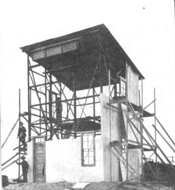
While the layout for sub-stations Nos. 3 and 4, which are located at Prosperity and Oronogo, is exactly similar to that of the two just described, the equipment is somewhat different. In the. two preceding sub-stations General Electric apparatus is used throughout. In sub-stations 3 and 4, high-tension switches of this make are installed, but the balance of the apparatus, including the transformers, switchboard, lightning arresters, etc., are of Westinghouse manufacture. The buildings, too, are of different design. In this case it has seemed desirable to build a structure which could be easily moved from one place to another, and to accomplish this a light steel framework has been designed and built in such form as will permit its readily being taken down. Fig. 10 is a view of sub-station No. 4, of the portable type.
The siding is of corrugated iron supported on angle iron, and the roof of wood sheathing lined with fireproof material and covered with corrugated iron. The whole structure is mounted on concrete piers, which also carry the weight of the transformers, the only weight necessarily carried in the building being the oil switches mounted on the second floor and the lightning arresters. With this form of construction, it becomes a very simple matter to take down the sub-station and move it to another point in the mining district in case the mines in the immediate vicinity become exhausted, resulting in a change in the center of distribution of the area supplied with power. In some cases this may be very desirable, on account of the mining conditions peculiar to the Joplin district.
Secondary lines are run from these sub-stations to the various mills served by the company. These lines are mounted on standard 35-foot poles. A four-foot six-inch cross-arm is placed at the top of the pole and beneath it a four-foot two-inch cross-arm. This makes it possible to carry two three-phase lines on each pole. For secondary transmission bare copper wire or cable of requisite size is used, the sizes ranging from No. 0000 down to No. 1, depending upon the load and the distance of the load from the sub-station. In case two lines are not to be installed at once, only the upper cross-arm is put in place, and the three wires of the transmission line first installed are arranged in a horizontal plane on this cross-arm. In case the second line is added, it simply becomes necessary to install the lower shorter cross-arm and the additional insulators. It is probable that when two lines are installed, the ordinary delta arrangement will be adhered to, although for practical purposes the inductive drop, due to placing the three wires of the transmission line on one horizontal plane, is not at all serious.
TELEPHONE SYSTEM.
A private telephone system has been installed, with telephones located in each of the four sub-stations and in the generator room and transformer house at the dam. The telephones are very carefully insulated from the walls, and insulated stools are provided, to be used when talking over the telephone. For lightning protection an ordinary 2,000-volt lightning arrester has been installed on the telephone line just as it enters the building. The telephone line next passes through the ordinary telephone fuses and then through sneak-current coils. which are also grounded, and finally through the small lightning arrester on the telephone. A double-pole single-throw knife switch is installed between the telephone and the sneak-current coil, thus making it possible to disconnect the telephone from the line. An extension bell is permanently connected to the line. This arrangement is made with the idea that the telephone can ordinarily be disconnected from the line, and the attention of the operator can be attracted by means of the extension bell. The operator can then close the knife switch,
thus putting the telephone in service, after which a conversation can be carried on. This precaution is taken with the idea that the telephone itself may be protected from any accident that may happen to the line.
MILL EQUIPMENT.
The standard mill equipment might be said to consist of a 15-horsepower hoist motor, a 10 or 15 horsepower pumping motor and a 50 or 75-horsepower mill motor with, in some cases, a 75 or 100-horsepower compressor motor. In cases requiring motors of 50 horsepower or over, 2,300-volt motors have been chosen. In such cases the motors are protected by automatic oil switches. Motors of smaller horsepower are 440-volt motors, and suitable transformers are installed for supplying current at lower voltage to all such motors. These motors are generally of the squirrel-cage type and are operated by the starting compensator. A typical installation for one of the mills is shown in Fig. 4. A 2,300-volt polyphase recording wattmeter is connected to the line at its entrance to the building. The large power motors operating at 2,300 volts are each controlled by its own automatic switch as well as the tap from the main service box which leads to the transformers reducing the voltage to 440 volts. Leads are taken from the secondary transformers to the starting compensators of the various 440-volt motors. In case a small amount of lighting is to be done, a single-phase transformer can be connected across one phase, and sufficient current for this purpose can be transformed to 110 volts.
OPERATION.
Sub-stations No. I and No. 2 have recently been put in operation and are furnishing power regularly to the mines now equipped with motors. The motors are rapidly being installed for the balance of the Spring River Power Company's customers, and all four sub-stations will soon be in service. The plant will be operated for the Spring River Power Company for the coming year by The Arnold Company.
The work of construction has been done under the immediate supervision of Mr. William H. Rosecrans, civil engineer for The Arnold Company, who has been in charge of all hydraulic features of the work. Mr. P. L. Battey, electrical engineer for The Arnold Company, is now in charge of the installation work and has superintended all the electrical construction work.
