[Trade Journal]
Publication: Western Electrician
Chicago, IL, United States
vol. 38, no. 8, p. 158-159, col. 1-3
Warren and Jamestown Single-phase
Railway.
The electric railway which has recently been opened between Warren, Pa., and Jamestown, N. Y., serves a total permanent population in adjacent territory of upward of 65,000 inhabitants. The equipment is thoroughly modern, comprising horizontal gas engines as prime sources of driving power, and the single-phase alternating-current system of the Westinghouse company. It is believed to be the first instance of a single-phase electric railway operated by gas engines. The current is generated in a power house without a boiler plant, transmitted at a potential of 22,000 volts over bare copper wires to transformer stations operated with-out attendants, fed to the central trolley section at 3,300 volts, to the terminal sections within the city limits at 550 volts, and is utilized most effectively in cars of handsome design.
TRACK.
The track is well constructed. The 70-pound rails are laid on ties of oak and chestnut and ballasted with gravel. They are connected by the type-G form 2 soldered bonds of the Ohio Brass Company, and are cross-bonded at frequent intervals.
As the line follows the winding course of the Conewango it possesses many curves, which together with the grades — one of which is three-fourths of a mile long, with an average of 3½ percent. and a short stretch of seven per cent. — combine to bring out the qualities of the operating equipment. The sharpest curve has a radius of 65 feet. Four turnouts are now in use, but this number will soon be increased to five.
The car barns are at Warren, Pa., and Frewsburg, N. Y., the repair shop being in the former.
POWER PLANT.
The power house is located at Stoneham, five miles south of Warren, that site having been selected by reason of its proximity to the natural-gas pipe lines, from which its fuel supply is obtained. The equipment includes two 260-kilowatt 380-volt 25-cycle alternating-current generators of the revolving-field type, which are direct-connected to horizontal gas engines operating at a speed of 150 revolutions per minute. The two units are connected in parallel and run together with remarkable smoothness. The engines were constructed and erected by the Westinghouse Machine Company, and the electrical machinery was furnished and installed by the Westinghouse Electric and Manufacturing Company.
GAS ENGINES.
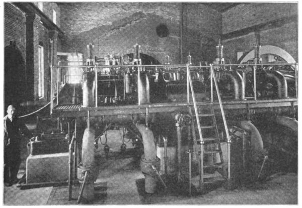
In the new type of horizontal double-acting gas engine the first representative of which is now operating at Warren, the builders have specially sought to construct a prime mover best suited from all standpoints to the American market — uncomplicated in design, simple to operate, substantial and permanent in construction, reliable in its working and possessing the best economy compatible with the more necessary elements of simplicity. The resemblance to approved steam-engine practice is strong; in fact, the engine stands not as an example of radical change in structure, but as an adaptation to gas working of the ample steam experience of the builders in Corliss engines. Symmetrical design has been adopted wherever possible, notably in the cylinder casting, with its symmetrical valve chambers, and in the pistons.
| |||
| Gas Engine Driving Generator for Warren-Jamestown Single-Phase Railway. |
A relay governing system has been devised which has proven entirely adequate in respect to both regulation and parallel working and which places this type of gas engine upon the same plane with large Corliss practice.
The absolute necessity of accessible parts has largely influenced the design of the engine and resulted in its elevation to such height that all parts are above floor level. Inspection and cleaning, especially of cylinders, is possible without dismantling the engine.
Possibility of injury from neglect has been avoided by providing automatic auxiliaries, both oil and cooling water being delivered under gravity head, cylinder oil by positive pressure and compressed air for starting from storage reservoirs. The starting arrangement has proven particularly efficient, and with only two operations, viz., opening of gas and air valves, the engine automatically starts and comes up to speed under its own ignition without further attention. On large engines considerably less than a minute is required to bring the engine up to speed, and, if desirable, a number of engines in a station may be simultaneously started from one point within this period of time.
To insure the greatest degree of reliability a duplicate system of igniters is employed, with four different combinations in each combustion chamber. Any igniter may be replaced while the engine is in service, and in case of necessity any cylinder may be isolated for repairs during operation.
There are two main generating units at present installed at Warren, with space for a third of equal size that is, 260 kilowatts, or 500 nominal horse-power. Single-crank tandem units were employed in place of twin tandem units in order to give greater flexibility of operation, the former representing the standard adopted by the builders. The units have solid couplings between engine and generator and operate in parallel on the station load in precisely the same manner as ordinary steam-driven units. The familiar Beau de Rochas, or four-stroke cycle, is used, which, with the tandem arrangement, gives a power impulse with each successive stroke of the engine. Cylinders are 21 inches in diameter by 30-inch stroke, the unit running at a nominal speed of 150 revolutions per minute. For this particular service the engine is rated at 470 brake horsepower, with a maximum of 520 brake horsepower, giving a 35 per cent. overload capacity on the generator.
OPERATION.
The Warren plant was started on October 19, 1905, and has since been in continuous service, averaging 17 1/2 to 18 hours a day without developing the least trouble of a serious nature. Daily observations of the gas consumption of the plant furnish a striking indication of its extremely high economy. During the month of December, 1905, the cost of gas consumed by the interurban system averaged less than 50 cents an hour, or about 16 cents a car-hour for 35-ton interurban single-phase cars. At present the large gas engines operate both interurban and city systems, totaling 10 cars. During the week ended January 12th the cost of gas averaged less than 75 cents per hour, or 72 cents per car-hour for three interurban and seven city cars. With this combined operation there has been realized a saving of approximately 20 percent. in cost of gas over the independent operation of the interurban and urban plants, the former by the new horizontal and the latter by vertical-type engines.
Fuel gas is available from several different points and is clean and uniform in quality, averaging from 1,000 to 1,100 British thermal units total per cubic foot. Gas is obtained at a straight rate of 15 cents per thousand cubic feet, which places the cost of power so far below the usual figure that any other source of motive power is out of the question.
ELECTRICAL APPARATUS.
From the generators the current passes through a switchboard of blue Vermont marble panels, completely equipped with apparatus and controlling devices, to raising transformers of the Westinghouse oil-immersed self-cooling type, which transform the potential from 380 to 22,000 volts. The two feeders which leave the station are adequately protected by circuit-breakers of the fuse type, disconnecting switches, low-equivalent lightning arresters and choke coils.
The high-potential lines, of No. 6 bare copper wire, are carried on porcelain insulators of the Ohio Brass Company, known by the trade name of Locke No. 406, which are supported on chestnut poles. Each feeder connects with a transforming station, one of which is located 14 miles from the Warren terminal and the other 1½ miles from the end of the line in Jamestown.
TRANSFORMER STATIONS.
The transformer stations are made of concrete blocks and are of suitable size to permit a wise arrangement of the apparatus. They are similarly equipped, each containing two 150-kilowatt 22,000-3,300-volt lowering transformers of the oil-immersed self-cooling type, which are controlled and protected by fuse-type circuit-breakers and disconnecting switches in the high-potential circuits and by oil switches and enclosed fuses in the secondary lines, one of which taps the 3,300-volt trolley section, while the other feeds the city section of the trolley line through auto-transformers along the track, which reduce the potential from 3,300 to 550 volts. Both high and low-potential feeder circuits are protected by choke coils and low-equivalent lightning arresters, which are mounted in the trans-former stations. The apparatus is symmetrically arranged, that mounted on one side of the station being exactly duplicated on the other. The two transformers are connected in parallel. Each has sufficient capacity to carry the entire normal load and either may be readily cut out of service.
The transformer stations are operated entirely without attendants, and require only occasional inspection. The building is fireproof. It contains no moving machinery or apparatus and has adequate automatic protection, so that there is no likelihood of trouble other than the opening of a circuit-breaker because of excessive load.
TROLLEY LINE.
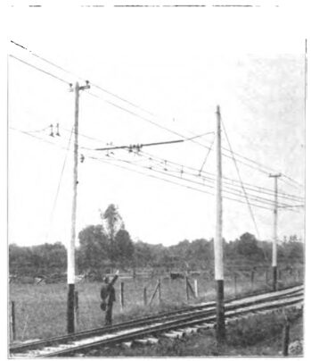
As has been indicated, the trolley line is divided into a central and two terminal sections. The central section is connected direct to the transformer stations receiving alternating current at 3,300 volts. A No. 0000 figure-8 trolley wire is swung by catenary suspension from a seven-sixteenths-inch messenger cable, which is carried on heavy porcelain insulators mounted on angle-iron brackets supported on the chestnut poles. The poles measure seven inches at the top and are 35 feet long. They are painted white and black, and present an attractive appearance. The white upper portions serve as useful guides to the line of the track during the darkness of night. All poles will be numbered to facilitate the location of line faults and other troubles.
| |||
| Track and Catenary Overhead Construction of Warren-Jamestown Single-Phase Railway. |
The overhead construction is particularly fine, as may be seen by reference to the illustration. A nice detail is the slight raising of one trolley wire at switch turnouts, as indicated in the illustration, so that the bow trolley easily passes from one wire to the other without impairment of contact. At frequent intervals the messenger cable is anchored, and steady-strain brackets are used at curves and turnouts. A few of the curves are constructed with pull-outs.
The catenary overhead-line construction is thoroughly substantial and reliable, and has not given the slightest trouble since erection . With such a line 3,300 volts is as easily handled as the lower potential of direct-current service with the usual overhead construction.
Within the limits of the terminal cities, the trolley lines are supplied with alternating current at the low potential of 550 volts. A feeder from each transformer station leads to three 75-kilowatt auto-transformers, which are located along the track, and connected to a No. 0000 secondary feeder which supplies the trolley. The auto-transformers reduce the potential from 3,300 to 550 volts. They are swung between pairs of poles.
| |||
| Baggage and Express Car on Warren-Jamestown Single-Phase Railway. |
The low-potential trolley line is supported from span wires by insulating hangers, in accordance with the practice standard for direct-current work. In Warren the new cars run over the tracks of the Warren Street Railway Company, which is equipped with the direct-current system. The two trolley wires, alternating-current and direct-current, are suspended side by side from the same spans with-out appreciably complicating the structure or in any way impairing the service of either system.
CARS.
The passenger cars are of the double-end, vestibuled, double-truck type, with 33-inch wheels and 5 1/2-incn axles. They measure 52 feet over all by nine feet in width, and seat 59 people. The seats are set crosswise along either side of a center aisle. They have high backs and are upholstered in green plush. The cars are supplied with bag-gage racks, signal circuits and many other modern features. A smoking, compartment is provided atone end and on the side. They are finished in mahogany and are decorated in excellent taste.
The operating company has at present five passenger cars and one baggage car, all of which were furnished by the St. Louis Car Company. Each is equipped with four Westinghouse No. 108 50-horsepower motors of the single-phase alternating-current, compensating, series type, mounted one on each axle, and connected by single-reduction gears. The motors are connected permanently in multiple and are operated by the hand-control system by means of taps from an auto-transformer, which supplies a varying electromotive force at the motor terminals. The controllers are of the drum type and closely resemble those of direct-current practice, though they occupy somewhat less space. They are mounted upon the platform at each end, so that the car may be operated in either direction.
A feature of this installation is its great simplicity and the small space required by the electrical apparatus. It consists only of one bow trolley, two standard wheel trolleys, two controllers, two canopy switches, one auto-transformer, two preventive coils with resistance, two fuse boxes, one change-over switch and the necessary connecting cable.
The bow trolley is used on the 3,300-volt section, the wheel trolleys on the terminal sections of the line. The change-over switch is arranged to cutout the bow trolley and transfer the connections of the wheel trolleys from the low to the high-voltage service taps of the auto-transformer, so that, in case of accident to the bow trolley, the wheel trolleys, which are mounted on heavy insulators, may be used on the 3.300-volt section of the line. The bow trolley is pneumatically operated, the controlling valve being mounted on the platform within easy reach of the motorman. The wheel trolleys are handled in the ordinary way with ropes, in which suitable insulators have been inserted to guard against the possibility of ground when used on a high-voltage circuit.
The preventive coils and resistances eliminate arcing at the controller contacts, when passing from one transformer connection to another.
The cars are equipped with Westinghouse straight air brakes, operated by means of an air compressor which is driven by a single-phase series-wound motor of a construction similar to that employed for the main driving motors. Hand brakes are also supplied.
The car, complete with equipment but without load, weighs approximately 66,000 pounds. The motorman has the car under complete control at all times. It accelerates rapidly and without the slightest jar. It runs smoothly, and, all in all, seems to operate in a most satisfactory manner. The alternating-current equipment responds readily to emergency demands, it being found possible to stop the car in a very short distance by simply throwing the reverse switch. As the controller handles are interlocking, the operating drum must first be thrown to the off position.
SERVICE.
The winter schedule requires the service of two passenger cars and one baggage car. Commencing at six o'clock in the morning, cars leave either end of the line every hour and a half ; this service continues until 11:30 p. m. The run of 222 miles is made in one hour and 10 minutes, each car laying over about 20 minutes between trips. There are 53 stations along the line at which stops may be made; their average run each way includes about 15 stops. The two cars pass at a switch near Ackley, about the center of the line. The maximum running speed is 50 miles per hour. The complete run from terminal to terminal, with-out stops, has been made in 47 minutes.
The change from the high to the low-voltage trolley is easily accomplished. As the car approaches the terminal section, the motorman re-leases an air valve, thereby lowering the bow trolley, which automatically closes down and locks in place. After passing the section insulator the conductor places the wheel trolley on the line in the ordinary way. The change-over may be made without stopping. Under present arrangements the car is run two days, with a mileage of 246, and is then brought in for inspection. The bow-trolley shoes are found to give a life of approximately 10,000 miles. So far there has been no indication of undue wear of the trolley wire, nor has there been any trouble with the overhead structure.
The baggage car makes three trips per day, on regular schedule, leaving Warren at 7:25 a. m., 11:40 a. m. and 4:15 p. m., and leaving Jamestown at 9:50 p. m., 2:30 p. m. and 7 p. m.
The present service of the Warren and Jamestown Street Railway Company requires a total of but eight employes, outside of the general offices and the car crews. It is made up of four men in the car barns, three power-house attendants, and one lineman. An additional lineman is occasionally borrowed from the Warren Street Railway Company. There are no attendants in the transformer stations.
PERSONNEL.
The officers of the company are: President, D.H. Siggins; vice-president, H. M. Preston; secretary, S. Q. Smith. Mr. Siggins is assisted in the management of the property by his son, H. A. Siggins, a director of the company and general manager of the Warren street railway. To President Siggins the community in which he lives is indebted for exceptional transportation facilities. His clear mind early recognized the possibilities of electric traction, and to his commercial courage and untiring energy is due the organization and success of the Warren Street Railway Company ,whose lines were constructed and have since been operated under his personal supervision.


