[Trade Journal]
Publication: Western Electrician
Chicago, IL, United States
vol. 36, no. 12, p. 223-224, col. 1-3
Bloomington, Pontiac and Joliet Single phase Railway.
Much interest has been manifested among engineers in the single - phase electric railway designed ultimately to connect the cities of Bloomington, Pontiac and Joliet, Ill. The distance between Bloomington and Joliet, which will be the two extremes of the completed line, is 90 miles, and forms one of the important links in the interconnecting system of electric railways which it is hoped will, before long, give direct service between Chicago and St. Louis. Already one can ride on electric cars from Chicago to Joliet. With the completion of the line now under consideration, Bloomington will be reached, making nearly one-half of the distance to St. Louis. A line already connects the city of Decatur with Carlinville, and electric service can also be had from Edwardsville to St. Louis. The only two links remaining, then, would be from Bloomington to Decatur and from Carlinville to Edwardsville, and these are now under contemplation.
Aside from its relation, however, to what will eventually be one of the most important electric railway systems of the state of Illinois, the system of the Bloomington, Pontiac and Joliet Electric Railway Company possesses many features of technical interest, it being the first single - phase road in the state and the third single - phase road of any kind to be put in operation anywhere in the United States. Thus far about 10 miles of the line has been put in operation, or that portion between Pontiac and Odell, to the northeast; from Odell to Dwight, still farther northeast, the construction work is now proceeding. The present article will treat of the completed section from Pontiac to Odell, which was opened to the general public for the first time on March 15th. One car only is as yet operated, which makes eight trips each way daily. Another car is under construction at the present time, and the two together will take care of the service until further extensions of the system are completed.
| |||
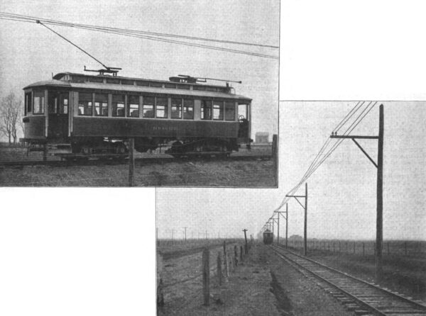
| Fig. 1. View of Exterior of Car. and Fig. 2. Catenary Construction of Trolley Line. Bloomington, Pontiac and Joliet Single-Phase Railway. |
The General Electric Company's single - phase system of electric - railway operation has been employed, and the general characteristics are similar to those of the Ballston single-phase railway in New York state, which was described in the Western Electrician of August 27, 1904. In the present case, however, there is not the problem of direct-current city operation to be considered.
ROADBED AND OVERHEAD CONSTRUCTION.
Observing Fig. 2 of the accompanying illustrations, a straight-away view of a portion of the line a short distance from Pontiac is obtained. All work on the roadbed has as yet not been completed, but the road will compare favorably with steam-railroad practice. The maximum grade is one per cent., which occurs at but one point. The rails weigh 70 pounds to the yard and are American Society of Civil Engineers standard cross-section. They are bonded with General Electric ribbon bonds, corresponding in cross-section to a No. 0000 copper wire. The rails are also cross- bonded every 1,500 feet.
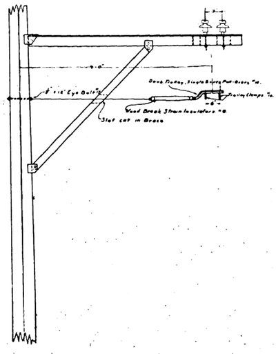 |
| Fig. 3. Bracket Construction and Pull-Over Used on Pontiac-Odell Single - Phase Line. |
The trolley wire is supported by a catenary construction, as shown in Fig. 2, the supporting steel wires acting also as conductors. The line is in duplicate, to avoid complication at switching points and also to avoid delay in case of breakage of one of the wires, the other wire being always available. The steel supporting wires are three-eighths inch in diameter and are carried by poles placed 100 feet apart. The insulators for the two parallel lines are placed seven inches apart, center to center, on the bracket arms. Suspended from the steel catenary wire is a No. 00 copper trolley wire. As shown in the picture, this is suspended from the steel wire at one point only, midway between each two poles. As soon, however, as the weather has become warmer, and the wires have expanded as much as they are likely to, suspension wires from the catenary to the trolley wire will be put in. The construction of pull - overs used on curves is shown in Fig. 3. Here is also shown the typical bracket construction for carrying the insulators. The total cost of construction of the line was $16,000 a mile, which included everything connected with the overhead work and the track. The cost of the pole line, including poles, wires, insulators and labor, was $2,550 a mile.
CAR EQUIPMENT.
Fig. I is a good illustration of the car now in operation. In general dimensions it is 41 feet eight inches long over all by eight feet 7-1/2 inches wide. The roof is of the monitor-deck pattern, the full length of the car body, with the trolley boards suitably fitted on the top. There is a brake shaft mounted on each platform provided with a vertical ratchet brake wheel for emergency use.
Inside, the car is finished in cherry. The seats have high backs and are done in green leather, 16 being in the main compartment, and the smoking compartment being provided with longitudinal seats. A hot-water heater is installed.
The car, which was made by the American Car Company of St. Louis, is mounted on Brill trucks with 34-inch wheels, the wheel base of each truck being six feet. All up-to-date features have been supplied to the car, such as air brakes, trolley retrievers, enclosed arc headlight, etc.
Most interesting from an electrical viewpoint, of course, is the motor equipment. Four 50-horse power single-phase motors furnish the necessary power for the car. These are connected two in series permanently, and are fed by the secondary of an 80-kilowatt self-cooled step-down transformer. The motors are each wound for 200 volts and are fed from five taps on the transformer secondary. A difference of potential of 400 volts is obtained on the last tap of the series, intermediate voltages of 350, 300, 250 and 200 volts being obtainable. During the transition of the controller point from one tap to the next there is no serious arcing, as coils of very high resistance are placed intermediate to the taps and the ground, effectually damping the arcing effect, which would otherwise be serious. With this arrangement the motors run at practically the same efficiency on any speed, which is one of the important points of advantage which the single phase equipment has over direct - current operation, effecting a large saving of current over that which the ordinary motorman will use with direct- current motors.
The weight of the motors is approximately 4,200 pounds each. On the roof of the car are located the high-tension fuses and the copper ribbon fuse which protects the transformer. A 2,000 - volt lightning arrester protects the car, and the trolley base, is supported by the necessary insulators to give protection from the high pressure of 3,300 volts which is used on the line. The trolley poles are two in number, 12 feet long and equipped with high speed wheels.
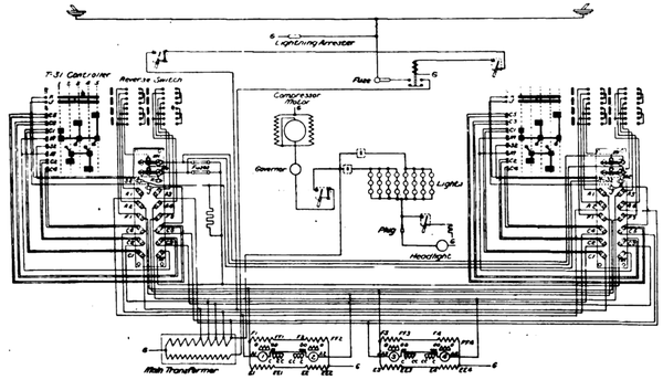 |
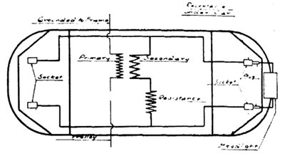
| Fig. 4. Diagram of Wiring of Single-Phase Car of Bloomington, Pontiac and Joliet Railway. |
Between the trolley and the ground there is mounted on the car a no-voltage-trip oil switch, the tripping solenoid of which is wound oppositely to that of the ordinary circuit breaker which is intended to open the circuit at a certain overload. The no - voltage switch is so arranged that the solenoid plunger is held away from the tripping device by the normal action of the current. If the pressure fails or falls below a certain point, however, the coil lets go and the plunger, through the action of a spring, trips the switch. The diagram in Fig. 4 shows the connections of the motor wiring, and by tracing the circuits a more correct idea can probably be obtained of the general arrangement of the apparatus than can be had from the description given above. The diagram represents the latest development in the system, which is as yet in the transitory stage.
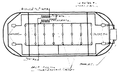 |
| Fig. 5. Lamp- Resistance Circuit of 25 - Cycle Arc Headlight. |
 |
| Fig 6. Car Circuit of 25 - Cycle Arc Headlight. |
Figs. 5 and 6 are the connections for the 25-cycle alternating enclosed arc headlight, showing, respectively, the lamp-resistance circuit and the car connections. The resistance lamps shown in Fig. 5, which also serve for lighting the interior of the car, are of 24-candlepower, 115 volts, and are connected in groups of three in series. Current from the trolley passes through the primary to ground on the frame. Current from one terminal of the secondary is conducted through the arc of the headlight and back through the lamp resistance to the other terminal, the scheme being shown more clearly in Fig. 6.
POWER PLANT.
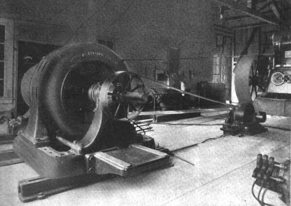
Power for the road is procured from a temporary installation located in the power plant of the Pontiac Light and Water Company, located near the heart of the city on the bank of the Vermilion River. Fig. 7 is a view in the interior of this plant, showing the railway generator. The generator is of the General Electric make, and is a 25 - cycle machine delivering 53 amperes at 3,300 volts, with a speed of 500 revolutions a minute. It is a three-phaser and was installed instead of a single-phase machine for various reasons. Exciting current is obtained from a 122- kilowatt direct-current dynamo, belted to the shaft of the main generator, as shown in the picture, and runs at a speed of 1,360 revolutions a minute. The main generator is driven by a 25-inch triple belt from a Westinghouse 18 - inch automatic compound non - condensing engine, the diameter of the high - pressure cylinder being 18 inches and that of the low-pressure cylinder 24 inches, both developing about 500 horsepower. Steam for the engine is taken from the boilers of the light and water company. They are three in number, Stirling water-tube, of 250 horsepower each. At the side of the generator and partially shown in the picture is the temporary switchboard, sup plied with a Thomson voltmeter and ammeter, field rheostat, etc. On the back of the board is located a 300 - ampere electrically equipped oil switch with the necessary pressure transformers for the electrical tripping device of the switch. There is nothing of especial interest about this part of the plant, the apparatus not being put in with a view of permanent operation. As soon as the system has been extended sufficiently to warrant the outlay, a new and fully equipped power house will be erected for the exclusive operation of the road.
| |||
| Fig. 7. Three-Phase Alternator of Bloomington, Pontiac and Joliet Single-Phase Railway. |
ORGANIZATION AND PERSONNEL.
The Bloomington, Pontiac and Joliet Electric Rail way Company was organized January 1 , 1905, with a capital of $300,000. The officials of the company are as follows: President, J. A. Carothers; vice president, D. S. Myers; secretary, A. C. Folsom; treasurer, W. F. Van Buskirk; general manager, Fred L. Lucas; directors, J. A. Carothers, B. F. Harber, John McWilliams, Jr., John S. Murphy, D. S. Myers, E. M. Johnson, A. M. Legg. C. E. Legg and Dr. J. E. Covey. In the few days that the road has been in operation evidence of a bright future, financially, has been manifested. The road parallels throughout its length two steam roads, the Chicago and Alton and the Wabash. The former is the one indicated by the line of telegraph poles at the left in Fig. 2. The fare from Pontiac to Odell on the new electric line is 20 cents, considerably less than that on the steam roads, and in consequence of this and for other reasons some jealousy has been manifested on the part of the steam lines toward the competitor, and one of them has succeeded up to the present in preventing the electric road from crossing its tracks to reach the center of Pontiac. Everything is in readiness, however, to run cars clear in as soon as the legal proceedings have been concluded, and the track is all ready with the exception of a few rods across the steam road's right-of-way: In the mean time, however, the electric company is obliged to run free buses from the courthouse square out to beyond the steam - railroad tracks, a distance of about a mile, which is naturally a detriment to the traffic. In spite of this, however, the car in operation is running with good loads at every trip and the traffic has increased to about 250 fares a day.
All the engineering and construction work on the power and line equipment was done by The Arnold Company of Chicago. The General Electric Company has taken a great interest in this particular piece of work, as it embodies so much that is new and of the utmost interest to builders and operators of electric railways. Mr. J. S.: Pevear and Mr. G. H. Hill, two prominent engineers of the company, came from Schenectady to witness the opening of the line. Since the new car was brought from the factory the company has also had a capable man (Mr. R. Stearns) out from the factory, to stay with it till everything has been thoroughly tested and to observe carefully its action under operating conditions.
