[Trade Journal]
Publication: Electrical World and Engineer
New York, NY, United States
vol. 34, no. 3, p. 77-80, col. 1-2
Canadian Water-Power Electrical PlantsIII.
ELECTRICAL TRANSMISSION PLANT AT THREE RIVERS, QUEBEC.
BY E. M. ARCHIBALD.
THE St. Lawrence is fed by numberless streams, large and small, the majority of which lie on its northern shore in the province of Quebec. The source of these streams is in the great Laurentian Mountains, famous for their geology, situated parallel to and distant some 150 miles from the St. Lawrence.
In making this great descent in such a short distance we would naturally expect to find the streams exceedingly rapid; nor are we mistaken, for so rapid and wild are they that we are almost .compelled to believe that nowhere else can such hydraulic conditions.
|
Near the city of Three Rivers, Quebec, there is a small electric plant in operation obtaining power from one of these rivers, the Batiscan, which has been in uninterrupted operation, since its inception, May 12, 1897, transmitting electrical power to Three Rivers, seventeen miles distant, and as such takes its place amongst our long-.distance transmission plants.
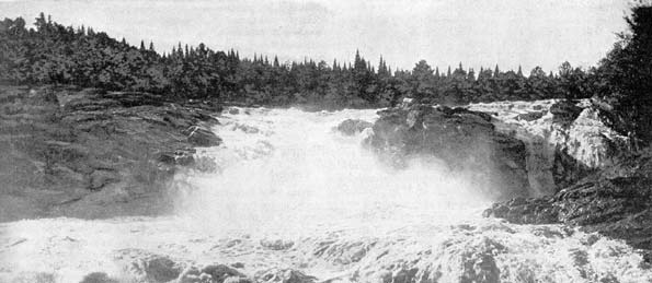
The Batiscan has its source far back amongst the numerous lakes on the highlands of the Laurentian Mountains, thus providing an unfailing water supply; and after winding around mountain, wilderness and dropping into peaceful valley, is finally stilled in the broad expanse of the St. Lawrence. At a point on this river known as the Grande Chute the water falls a depth of 70 feet in a distance of less than too yards, and on this account and also by reason of the natural advantages of the location, the situation of a power house is almost ideal.
Previous to 1897 the Corporation of Three Rivers had been doing all the incandescent and arc lighting by the use of steam engines in 'connection with its already existing water pumping system; but in so doing was running behind in its accounts every year, even though the charge for private lighting was at a comparatively high rate. After meeting several deficits, it was decided to dispose of the electric plant as soon as possible, and an offer made by the North Shore Power Company was favorably considered, duly approved and the transfer made, although at a considerable reduction in first cost. A contract was then made with this company for the street lighting.
The North Shore Power Company in looking around for a suitable water power in order to reduce the cost of operation, saw the advantages of and decided upon the Grande Chute on the Batiscan River near the French village St. Narcisse. Although this was seventeen miles from the city, the cost of dam, power house, equipment and transmission line was found to be comparatively small, so that by careful management a good profit could be realized. Accordingly, this power was purchased, operations immediately commenced and on May 12, 1897, without any interruption in the lighting service, the system of Three Rivers was changed from a single-phase distribution with steam generating plant in the city, to a two-phase distribution with water power plant, seventeen miles distant.
After obtaining the water power there was one of three situations to be decided upon for the plant location: Two of them each with a head of 70 feet, and the other with only 50 feet. Strange as it may seem at first sight, the latter was chosen on account of the small cost with, which a dam and power house could be erected in that location. Owing to volcanic action in ages long past, a natural dam had been formed extending the greater part of the distance across the river. This had to be extended and raised to such a height as to bring the level of the dam above the high water in spring time.
The general view of the property and power house is given in Fig. 1. In the right hand corner the dam may be seen extending towards the left, the lower part of which is the, spillway over which the water, ice, logs (lumbering being a great industry) and rubbish pass, the high part being the dam proper. At the junction of the dam and the spillway there is constructed a wall of masonry at right angles to the dam, acting as a prop to aid the dam in withstanding the pressure upon it. The dam is 11 feet thick at the bottom, tapering off to 3 feet at the top, and is built of masonry, the rock all being obtained from the bottom of the present head, race by blasting. This rock is similar to, but harder than, granite, and is to be found in large quantities at all the waterfalls in this neighborhood, but in no other place.
No trouble has been experienced from frazil ice, that bugbear to Canadian water power development, although the river has been full of it. The reason of this is that the frazil is all swept down by the very rapid current going over the falls, so that none enters the head race, and as this is completely frozen over all winter, frazil is out of the question, as it can only form in open rapids. This is the same plan that has been tried with success at Quebec and also at the Lachine Rapids near Montreal.
There are two head gates in the extreme end of the dam, nearest the power house, only one of which is in use at present. A rack of flat iron bars at the entrance to the head gate acts as a screen to prevent rubbish from entering the pipe. There is also a waste gate which can be opened more or less to get rid of accumulated rubbish.
PIPE LINE.
The pipe is made of 5-16 inch steel plate, 6 feet 6 inches in diameter and in 6 feet sections riveted together; the whole being embedded one-third of its depth in a rock foundation. Commencing at the head gate, into which it is securely cemented, it runs to the power house, a distance of 400 feet, in a perfectly straight line.
By being kept filled with water at all times, expansion and contraction have no great effects. A small effect, however, does exist, and this forces the turbines, which are directly connected to it, to move through a maximum distance of 3/8-inch from winter to summer. It becomes necessary then in order to preserve perfect alignment between dynamos and turbines, to shift the dynamos backwards or forwards.
At the termination of the pipe line, which passes directly under the power house, is a large head-sheet, in which is situated a 12-inch gate valve for purposes of draining the pipe when repairs become necessary. Directly under the wheel casings, a few feet from the end, two vertical branch pipes 5 feet in diameter are connected into the pipe for supplying the water for the turbines. A relief valve is situated midway between the two turbines for disposing of the imprisoned air, which becomes compressed to such an extent during a sudden rush of water that there is otherwise danger of bursting the pipe.
The tail water is normally at a depth of 12 feet below the centre line of the turbines, and in order to keep that depth constant, an overflow weir is built under the power house over which all the tail water must flow to the tail race beyond, a natural watercourse leading to the river below.
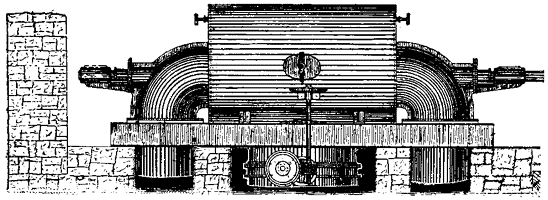
POWER HOUSE.
Nestling in a natural gulley, seemingly prepared for it, and surrounded by rough boulders scattered about promiscuously, between which the scant vegetation struggles for its very existence, is the power house, a rough stone, one-story building, 62 feet long by 36 feet wide, having for its foundation an enormous flat granite ledge.
| |||
| The Three Rivers Transmission Plant., Fig. 1. View of Power House., Fig. 2. Interior of Power House., Fig. 3. Wheel Cases in Power House., Fig. 4. Transformer Switchboard. |
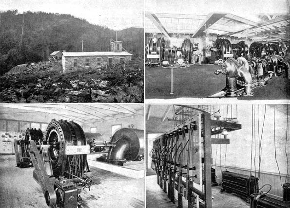
The interior (Fig. 2) is a great contrast to the outside surroundings, presenting a very neat, bright and cheerful appearance, the walls and roof both being painted white. Situated directly on the main floor are the two wheel cases (Fig. 3), built of 5-16-inch steel plate 6 feet in diameter and 6 feet in length, with heavy cast iron heads supported by I-beams on solid masonry. Terminating in the cast iron heads are two quarter-turn steel elbows, 2 feet 6 inches in diameter, forming the discharge pipes and at the same time providing a bearing for the turbine shaft, which passes entirely through the wheel case.
Situated in each wheel case are two 21-inch wheels on one shaft developing 200-hp each under a head of 50 feet and running at 400 r. p. m. By placing a wheel on each side, the water from the pipe line flowing between them and discharging outwards on both sides, the thrust is equalized, and a uniform twist is produced on the generator shaft, which is directly connected by means of an insulating leather coupling. This coupling consists of four links, each link containing six heavy sole leather strips bolted at each end to the turbine and generator shafts, respectively, thus permitting free operation even when out of alignment to a small degree, and also affording perfect insulation.
Situated in each branch pipe entering the wheel case is a butterfly gate operated by worm gearing for regulating the quantity of water entering the wheel; above this is a pipe with a stop-cock for completely draining the wheel case when necessary.
Regulation, which is all performed by hand, is also afforded by means of a worm gearing operating the guide blades, which may thus be set in any position desired.
These wheels, which are of the Crocker type, together with the steel flume, were supplied and installed by the Jenckes Machine Co., of Sherbrooke, Quebec.
The two generators, which are direct-connected to the turbines, are each of 240-kw, two-phase, S. K. C. system, supplying current at a frequency of 133 cycles per second and at a pressure of 2400 volts. This high frequency was adopted so as to change from the old single-phase system with its alternators and transformers designed for that periodicity with the least possible cost.
Belt-connected to each generator is a 4-pole, 10-kw, 50-volt Royal Electric exciter, running at 570 r. p. m., each being capable of fully exciting both generator fields. These generators are situated 15 feet apart, centre to centre, sufficient room being left for the installation of another generator of similar size.
A very neat little switchboard, consisting of three white marble panels on a hardwood frame, is used for regulating the above apparatus, and also for operating them in parallel. A portion of it may be seen in Fig. 2. The two outside panels are exactly similar, one for each machine, and contain a voltmeter and two ammeters for indicating the voltage and current on each phase, a small switch placing the voltmeter across either phase through a step-down transformer; two double-pole single-throw switches, one for each phase, of the ordinary slide type as used in the S. K. C. system; a double-pole, double-throw horizontal switch for connecting either one of the two exciters to the generator field; and lastly, two rheostats, one for the generator field, the other for the exciter. The middle panel contains the synchronizing lamps and switch. Three lamps are used, although only one is absolutely necessary, as the machines are coupled when the lamp is bright the two outside lamps being connected constantly to their respective machines and remaining constantly bright, the middle one being the synchronizing lamp.
From this switchboard the machine terminals are carried under the floor to the transformer board, situated at the upper end of the power house and separated from the main room by a glass partition. In this room are placed seven 60-kw Royal Electric transformers, four of them being each placed in a cylindrical iron case and air cooled by means of a draft tube, the remainder being of the ordinary type, and not used except when required by necessity. The voltage is raised from 2400 to 12,000, at which pressure it is transmitted to Three Rivers.
Both primaries and secondaries are controlled by switches on the transformer switchboard, Fig. 4, consisting of twelve panels of white marble, on each of which is placed a switch of the bayonet stick type for the primary side, and six smaller double-pole slide switches, each on separate marble slabs, for the secondaries. This switchboard has a frame of hardwood, so there is little danger from accidental contact. Its present size is for the proposed additional generator.
The centre panel contains the two static ground detectors of the Stanley type, with switch for connecting either to ground. On the back of the switchboard there are placed fuses of the D. & W. non-arcing enclosed type for protecting both the primaries and secondaries of the transformers. From this switchboard the wires pass to the line through choke coils, taps being taken off to lightning arresters of cylindrical non-arcing metal, similar to the Wurts', there being 30 gaps between each line and ground. All electrical apparatus, switchboards, instruments, etc., were manufactured and installed by the Royal Electric Co., Montreal, Quebec.
POLE LINE.
From the transformer board the four line wires pass through a cupola in the roof to the pole line, which leads directly up the side of a mountain, as seen in Fig. 5, passes through the bush, the trees being cut and burnt on each side to provide a clear path; traverses the public highway and along the Canadian Pacific Railway's right of way, crosses a bridge on cross-arms projecting from the side, and finally reaches Three Rivers, seventeen miles distant. This transmission line consists of four No. 4 bare copper wires, 18 inches apart, securely fastened to porcelain insulators of the triple-petticoat type, made by F. M. Locke, of Victor, N. Y., and tested to 45,000 volts. They are secured to the single cross-arm by 10-inch locust pins, which are extra long on account of the heavy snow and sleet which falls in this region.
| |||
| Fig. 5.Pole Line. |
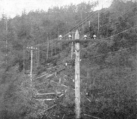
The poles of white cedar 35 feet in length, 7 inches in diameter at the top are spaced 95 met apart. For protection against lightning three barbed wires, one on top of the pole and one at each end of the cross-arm, run the entire length of the line, being grounded at every fourth pole.
A telephone line, of ordinary galvanized iron wire, is run on side brackets situated some distance below the transmission wires, and although transposed every fourth pole to prevent induction, it is present, however, to such an extent that Ericcson's anti-induction instruments had to be installed on each end of the line, the ordinary telephone instruments not operating successfully when the line was heavily loaded. The line loss is about 9 per cent. at full load, of which 2 per cent. is due to inductance.
SUBSTATION.
Reaching Three Rivers the line passes into a small transformer shed through choke coils to the switchboard, taps being taken off to lightning arresters of the Wurts non-arcing type, having 30 gaps between each line and ground. Passing through the high tension switches of the bayonet stick type, of which there are twelve, to the transformers, six in number of 60-kw each, the voltage is stepped down to 2000, the city pressure. Thence through the secondary double-pole switches to the regulator board in the substation proper, the transformers being protected on both the primary and secondary sides by D. & W. non-arcing enclosed fuses.
This substation is a brick structure formerly occupied by the corporation for its electric light plant. The present company is allowed the use of it for a certain period, the building not being included in the purchase.
The equipment consists of two T.-H. single-phase alternators with a frequency of 133 cycles per second and of 750 and 1500 lights capacity respectively; two T.-H. series arc machines of 30 and 50 lights capacity: two high-speed engines of 100 and 200-hp; two jet condensers and pumps, and four internally fired tubular boilers, all built by Leonard & Ball London. Ontario.
| |||
| Fig. 6. Interior of Substation., Fig. 7. New Switchboard in Substation. |
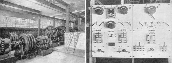
In the changes that have come about, the dynamos are all left in position ready to be belted directly to the engines as formerly, in case of a breakdown to the water power plant, but the 1500-light alternator has been turned into a synchronous motor taking current from one of the two phases, and drives the two arc machines for the street lights (Fig. 6). A two-phase, 1000-volt, 15-hp induction motor is used as a starter to bring the speed of the alternator up to synchronism with the generating units. Belt-connected to the countershaft is a bipolar dynamo for exciting the fields of the synchronous motor.
 |
| Fig. 8. Crocker Turbine. |
The new switchboard, Fig. 7, consists of two panels of white marble on a hardwood frame, built and installed with the rest of the electrical apparatus by the Royal Electric Company, of Montreal. The right-hand panel is for the control of the synchronous motor, the ammeter at the top indicating the amount of current consumed by the motor, under which is placed a short circuiting switch for cutting out the ammeter during operation. The ammeter is only of use in properly adjusting the field so that it takes the least amount of current. Below are the synchronizing lamps, on either side of which are situated duplex fuse blocks, so arranged that should one blow, the other may be brought into service by simply turning a switch. The double-pole main switch for the synchronous motor, the four-pole, two-phase switch for the starting motor, the field rheostat and field switch are placed on the lower part of the same panel, and may be seen in the illustration.
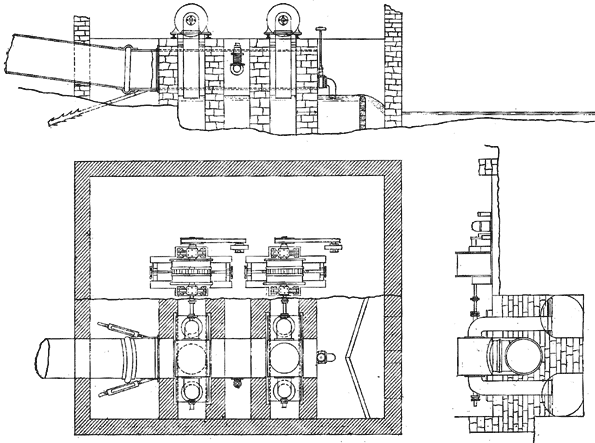 |
| Fig. 9. Elevation and Plans of Power Generating Plant. |
On the left panel are situated the two ammeters, one for each phase; static ground detector and voltmeter, each capable of being connected on either circuit by a switch placed underneath; duplex fuse blocks, one for each circuit; two main double pole switches and two transformer regulator heads. These latter vary the rate of transformation of two transformers, one in each phase, by cutting in or out more or less coils, in this manner producing the correct voltage, and hence a uniform light.
Notwithstanding the alteration from a single to a two-phase system, which was done without any interruption to the lighting service, all the old apparatus and lines are still in use, except the 750-light alternator, which is idle, so that the change was performed at a minimum cost.
The French "habitants" of Three Rivers are very conservative about changes, still clinging tenaciously to their oil lamps, so that the field covered by the incandescent lamp is not as extensive as it deserves; nevertheless, it is slowly but surely increasing. There being no motors in operation on the line, the plant is only in operation from about 5 p. m. to 5 a. m., or from sunset to sunrise.
Current is still furnished at the flat rate of $4 a year for churches, Public places and residences, and $5 a year for shops for the first lamp, with a sliding scale as low as $3 a year for each additional lamp above a certain number. Some few wattmeters are, however, installed, the number of watts used being divided by the voltage, 104, to reduce to amperes, the rate being 1 cent per ampere hour. At a meeting of the directors to be held shortly, a discussion will take place as to the advisability of introducing meters altogether and charge by the kilowatt-hour.
The officers of the North Shore Power Company are: Hon. C. C. Colby, president; P. E. Panneton, vice-president, and John B. Frejeau, managing director, to whom the author is much indebted for facilities afforded.
