[Trade Journal]
Publication: Electrical World
New York, NY, United States
vol. 30, no. 20, p. 589-592, col. 1-2
A Sierran Transmission Plant. (1)
BY GEO. P. LOW.
High in the Sierra Nevada range in Central California, almost directly east of Stockton, are the Blue Lakes. Their elevation above the sea level is some 8000 feet, only 1000 feet below the crest of the range. They drain a catchment area of several thousand acres, and are fed by great fields of snow and rushing torrents from the slopes above them.
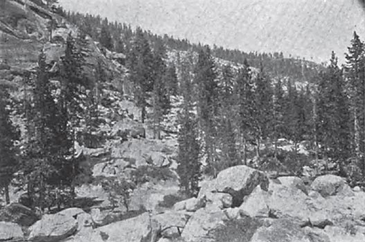
| |||
| A Characteristic View in the Catchment Area. |
The Blue Lakes Water Company was incorporated in 1890 to develop and distribute water-power for mining operations in Alpine, Amador and Calaveras counties and the neighborhood thereabouts. This part of the State is memorable for the mammoth hydraulic works that for many years tore away its hillsides, washed the earth through sluices and left a country of boulders and gulches similar to the moraines of glacial action. Plenty of gold, however, was left in the soil and the mother lode. This gold has never been obtainable because of the high cost of fuel, wood being cheaper than coal, and that at about $5 per cord. All that is needed for the development of many paying mines is power. This the Blue Lakes Water Company undertook to obtain from the streams flowing through the mountains. The company has a capital stock of $10,000,000, and is authorized to issue $5,000,000 in bonds. Of this amount $725,000 has been issued and $600,000 has been paid in for stock.
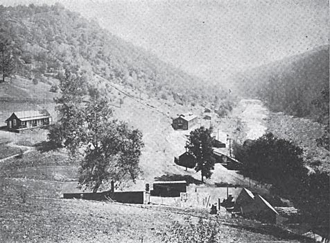
| |||
| General View of Blue Lake City. |
The company now owns all the available lands surrounding the lakes and reservoir and along the rivers, canals and ditches which it uses. Its main reservoirs are the Blue Lakes, high in the mountains, the storage capacity of which has been greatly increased by the building of dams. Upper Blue Lake has been confined by a masonry dam 250 feet long, 25 feet high and from 30 to 50 feet-in- width, giving the lake an area of 375 acres. Lower Blue Lake has also been enlarged by a crib-work dam with earth filling. The water from the lakes is discharged into Blue Creek whence it flows through various natural waterways for a distance of 40 miles, falling in that distance almost 6000 feet. Various auxiliary streams and storage ponds adjacent to the route are also tapped. The natural water ways used run through almost their whole course over solid granite, so that there is practically no loss of water from seepage and but little loss by evaporation, owing to the velocity of the stream and its consequently small surface. At a height of something over 2000 feet above sea level the water enters the Amador Canal. This artificial waterway is 42 1/2 miles long, the first half being a flume running along the steep, rocky slopes of the main canon of the river. Eighteen miles below the head-gate the canal leaves the canon, passes through a short tunnel and enters a region of clay and gravel, through which it runs as a ditch to its terminus in the Tanner reservoir. The canal has a grade of 8 feet per mile, giving an average velocity of flow of 300 feet per minute, which, when full, gives a capacity of about 3000 miner's inches of water.
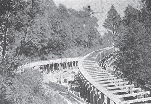
| |||
| A Flume on the Amadore Canal. |
The water delivered through the canal is used for the general supply purposes of various towns and villages in the neighborhood of Blue Lakes City, as well as for the company's electric power plant and the operation of a number of mines. Near the lower end of the canal are several reservoirs, which, when improved, will contain sufficient water to supply the whole system continuously for over a week, if the canal should be totally out of service for that length of time. The ditch feeding the pipe line to the power plant ends in a massive concrete structure serving as a combined forebay and settling basin, the whole construction being of the most durable type. Connected with this forebay is a spillway, which discharges waste water down a canon other than that used by the pipe line. The pipe-hoc supply is taken near the surface, and carried through double sets of strainers before entering the pipe. The pipe line itself is 3240 feet in length. In plan it follows an absolutely straight line down the surface of the rock from the penstock to the power house. The average slope is such as to give a head at the wheel nozzles of 1040 feet. The first 800 feet of the pipe line consists of a thin steel, slip-joint pipe; the next 900 feet of riveted steel pipe, ranging in thickness from one-sixteenth to one-fourth of an inch, joined by cast-steel flanges. The final section of 1500 feet is made of lap-welded steel pipe, of a thickness of three-eighths to one-half an inch. Cast-iron socket flanges are used, packed with sheet-lead gaskets highly compressed. The inside diameter of the pipe line varies from 24 inches to 21 inches. The mountainside on which the pipe line is laid is covered with soil of varying thickness sup to 25 feet. To prevent any possibility of injury from landslides, the pipe is laid on bedrock throughout its entire length, and cemented thereto. For 400 feet at the tower end of the pipe line, a trench was blasted out of solid rock, and the pipe was cemented in place with concrete filling. At each joint for about two-thirds of the distance up the hill the pipe is anchored to the bedrock in cement. The lower and of the pipe terminates in three cast-steel "Y" branches, which lead direct to the water wheels. The walls of these Y's are one-half inch thick.
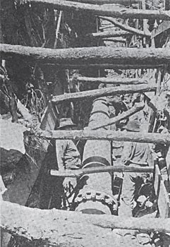
| |||
| A Deep Cut on the Pipe Line Trench. |
The most important feature of the hydraulic system is the fact that there is no receiver or air chamber. The gales in the plant are so built that it is impossible to open or close the main gate in less than ten minutes' time; nor can any of the four nozzles be opened or closed in less than three minutes' time. It is believed that this arrangement will prevent any possibility of water ramming. The governing will be effected by hooding two of the four nozzles of each wheel, the remaining two being provided with manually operated throttle valves. The diver-ion of the stream from the wheels by a hood will, of course, make no difference in the discharge rate so that there will be no water ram front that cause. At present the wheels are governed solely by hand.
| |||
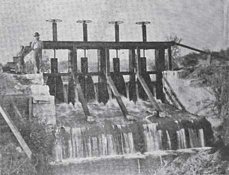
| A Mountain Head-Gate. |
The power house is a substantial building 35 x 100 feet in size, the present machinery only filling one-half of this space. The structure is longitudinally divided into two levels, the upper or switchboard level being 8 1/2 feet above the floor level, on which is placed the main machinery. Part of the space for the building has been blasted out of solid granite, the stone so removed being used in the walls The generator and water-wheel foundations rest on granite at a depth of 9 feet. The building proper of steel-frame construction and covered in a rather peculiar way. Over the steel tram is stretched wire netting on all sides and the roof. This netting supports two layers of asbestos paper, over which are laid two layers of tarred paper, which is finally covered with heavy corrugated iron. The paper is intended to prevent condensation. A 10-ton traveling crane traverses the whole of the generator room, which, being painted white, presents a pleasing appearance.
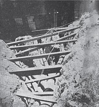
| |||
| Y-Branches at Foot of Pipe Line. |
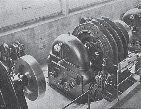
The water is led from the Y castings to the main gates of each of the three wheels through 15-inch pipes. Each gate is operated by a worm and worm wheel, the worm wheel being fixed to the nut on the valve stem. This gives such a speed reduction that it is impossible to move the valve rapidly. The worm wheel is inclosed in the pressure chamber, which eliminates the necessity of packing. The water wheels are of the impulse type, 4 feet in diameter, and were made by the Abner Doble Company, San Francisco. These wheels run at 600 revolutions per minute, and are rated at 700 horse-power each. They are incased in cast-iron housings of an exceptionally neat and simple appearance, as shown in the illustration. The wheels are direct-coupled to the generators, the end of the shaft on the other side of the generator carrying a 4000-pound fly-wheel. The shaft runs in two bearings only, the fly-wheel overhanging one end and the water wheel the other end, the armature being between the two bearings. The rotating parts of the generator weigh, all told, about 20,000 pounds, which gives considerable moment of inertia to help in the speed regulation.
| |||
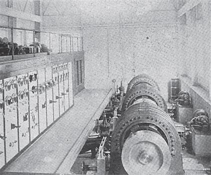
| The Interior of the Power Station. |
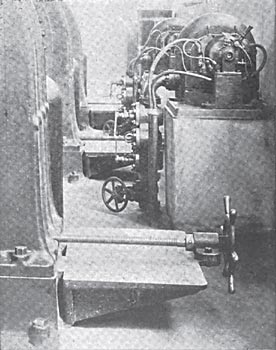
The dynamos are 450-kw Stanley two-phase, inductor type machines, delivering current at a frequency of 60 cycles per second, at a potential of 2000 to 2400 volts. These generators being of the standard Stanley type, are too well known to require detailed description. Two exciter sets are provided, each consisting of an 18-inch Doble wheel direct-connected to a 10-hp dynamo. These are located on concrete piers to the rear of the generators. The jets of the small wheels working on this high head are of such a small diameter that there is risk of small chips of wood or twigs stopping them up. To provide for this the water delivered to them is passed through strainers made of brass gauze and mounted in cartridges which are easily removable. Two cartridges are provided, with a two-way valve, so that either may be used while the other is removed. The exciters generate current at a pressure of 60 volts, either exciter having a sufficient capacity for energizing the fields of all three of the main generators.
| |||
| The Exciter Sets Showing the Strainers. |
The main switchboard is provided with two sets of four-pole bus bars, each main generator switch being four-pole and double-throw, so that either generator can be worked singly or both in multiple, on either or both sets of bus bars. Power is delivered at present to two transmission lines, one of which is supplied by contract with the California Exploration Company. Two Thomson recording wattmeters are mounted on the switchboard, one of which measures the power delivered to this contract line and one to the line of the water company itself. The switchboard is fitted with ten panels, several of which are not in use as yet, but will come into use as the different transmission lines are added. One of these lines will extend to Stockton, 39 miles distant. The switchboard is fitted with synchronizing apparatus, consisting of the usual transformers, whose secondaries may be connected in series and thrown on lamps. The only part of the synchronizing equipment that appears on the front of the board is a small, U-shaped plug, by means of which the combinations of the secondaries of the synchronizing transformers are changed to indicate synchronism between any two of the three generators.
| |||
| One of the Wheel and Generator Sets. |
The voltage to be used on the circuits now erected is 11,000 volts, but the step-up transformers have not yet been installed, and a pressure of 2400 volts is delivered direct from the generators. Before spring, however, the high voltage will be put on the line. From the high-potential panels the line circuits are carried to choking coils beneath the roof frames. These choking coils are made by winding 200 feet of No. 3 insulated wire into coils measuring about 24 inches in diameter. Between them and the outside lines are the Wirt alternating-current, short-gap lightning arresters. Five of these arresters, which are designed for 2000 volts each, are connected in series between each line wire and a graphite resistance of 400 ohms, which is connected with the ground. The gap between the arrester cylinders is one-thirty-second of an inch. The design of the device is such that the arc is extinguished upon reversal of the current by the cooling effect of the large metal cylinders.
The pole lines carrying the transmission circuits arc of the most substantial type. Thirty-five-foot selected red-wood poles are used, measuring 10 x 10 at the butt and 6 x 6 at the top, and sunk 6 feet in the ground. Two 22-inch cross arms are placed 18 inches apart, and at curves are doubled and framed together. All poles on curves are firmly guyed. Two No. 3 B. & S. gauge bare wires arc placed on each cross arm, 18 inches apart, each phase being carried by the wires diagonally across the square. Locke triple-petticoat porcelain insulators are used. The lines are not transposed. Over the tops of the poles, supported on porcelain knobs and grounded at intervals, is run a close-barbed galvanized-iron fence wire for lightning protection. The line is run through a rugged country, so that the distance between poles varies from 50 feet to 125 feet. On nearly its entire length the pole holes were blasted in solid rock.
 |
| Sectional View of Power House. |
Power has been supplied to various mines in the vicinity for some time by ditches branching from the main canal, and carrying water to the wheels at the mines themselves. As the elevation differs at the various misses. the power output per cubic foot of flow was a very variable quantity, and its case of high elevation no power could be delivered in this way. These local water wheels will now be replaced by motors deriving their power from generators in the main station. It is estimated that between 1500 and 2000 horsepower will shortly be used by the mines situated along the, mother lode in Amador County. The cities of Jackson, Sutter Creek and Amador have heretofore been lighted from a central station located in Sutter Creek, driven by water from the canal. The lighting systems has now been changed over and put on the 2,400-volt generators direct, the load amounting to about 300 horse-power.
The power plants for utilizing the electric power in the mines have not as yet been installed. In some instances large induction or Synchronous motors will be belted direct to the main shafts in place of the present water wheels, while in other instances, small units will be distributed throughout the works. It has been proposed to run steam engines where such are in place, as air motors fed by air compressed into receivers. consisting of the present steam boilers, by [spell: compressers, compressors] run by two-phase motors. It is hardly likely, however, that anything will be gained by this multiplex transformation arrangement. The use of the two-phase motor in place of the steam engine would be far preferable, except possibly in instances where intermittent power for brief periods only is necessary.
(1) Abstract of a paper in the Journal of Electricity, Oct., 1897.
