[Trade Journal]
Publication: Electrical World and Engineer
New York, NY, United States
vol. 46, no. 18, p. 729-735, col. 1-2
Development of the Necaxa, Mexico, Water mile.
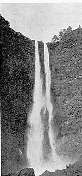
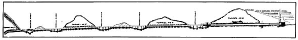
ONE of the most striking and interesting developments of water power that has recently been carried out in the Republic of Mexico is that connected with the utilization of the Necaxa Falls by the Mexican Light & Power Company under the initiative of Dr. F. S. Pearson. This great enterprise has as its field of operation the great central Mexican plateau, where it is developing and conserving the energy of the Tenango and Necaxa Rivers. At a point 100 miles northeast of the City of Mexico these rivers debouch from the mountain chain at a height of about three-quarters of a mile above the sea, their joint flow being discharged finally into the Gulf of Mexico. An idea of the region and power is given in Figs. 1, 2, 3 and 4. These two rivers drain jointly an area of about 227 square miles, and on account of the geological nature of the plateau encountered a remarkable succession of waterfalls resulting in a total drop of more than 3,000 feet in a distance of three miles. The plan adopted for the utilization of the water power thus available is indicated roughly in Figs. 5 and 8. The Tenango River has been consolidated with the Necaxa by diversion and their joint flow has been stored in a reservoir lake at Necaxa, as indicated in Fig. 8. From this reservoir by a tunnel and pipe line, as indicated, the water is carried to the first power plant with a total drop of 1,470 feet in a mile.
| |||
| Fig. I.-The Second Necaxa Falls. |
| |||
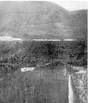
| Fig. 2.-Tenango Falls, Mexico. |
It is thus utilized at the first power house shown in Fig. 8, but will ultimately be utilized again at the end of another drop of 1,100 feet. The two plants are to have a final capacity of not less than 80,000 hp. As indicated in Fig. 6, the power is to be carried by a transmission line from the first power house to the City of Mexico, and also far beyond that point to the mining district of El Oro, giving a total line transmission of 171 miles.
| |||
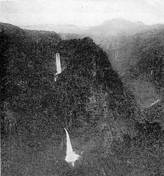
| Fig. 3.-General View of Necaxa Falls Region and Construction Camp. |
| |||
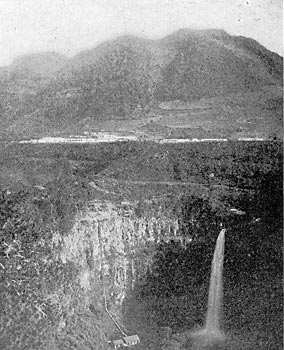
| Fig. 4.-Temporary Plant and Cableway at First Necaxa Falls. |
| |||
| Fig. 5.-Profile of Pipe Line. |
 |
| Fig. 6.-Route of Transmission Line. |
| |||
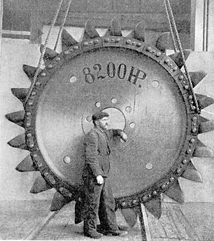
| Fig. 7.-Impulse Wheel Employed at Necaxa. |
 |
| Fig. 8.-Map of Transmission Line and Pipe Line. |
| |||
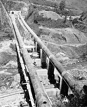
| Fig. 9.-View of the Pipe Line From Tunnel No. 5. |
| |||
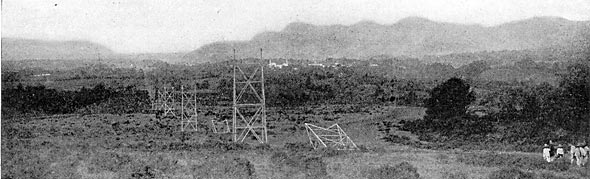
| Fig. 10.-General View of Country and Transmission Line. |
| |||
| Fig. 11.-View of Twin Lake, Near Mexico City. |
| |||
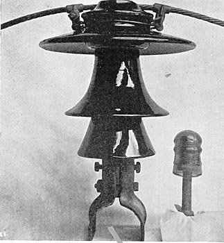
| Fig. 12.-Comparative View of Main Line and Telephone Insulators. |
| |||
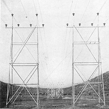
| Fig. 13.-Side View of Necaxa Transmission Line. |

| |||
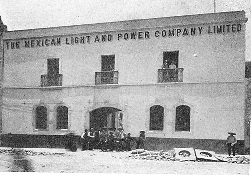
| Fig. 14.-New Sub-Station for Necaxa Power, City of Mexico. |
The engineering involved is of a most able and ingenious character, and the plant when completed to its full capacity will present many features of surpassing interest. The dam of the Necaxa Lake is of earth 177 feet high and 600 feet long, with a base width of 950 feet and a width of 54 feet at the top. No less than 2,000,000 cubic yards of material were required for the wall, obtained chiefly by blasting. A three-square-mile lake has thus been created from which the impounded water is carried off by means of two pipe lines, as shown in Fig. 9, running in a series of tunnels 1,500 ft. long. Beginning with two vertical intakes with gates at different levels, these pipes end in a receiver from which six seamless steel tubes are carried to the power house itself.
| |||
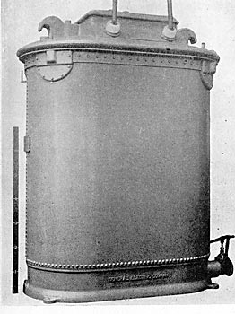
| Fig. 15. - Necaxa Step-Up Oil Transformer. |
The horizontal penstocks are 8 feet in diameter and 3/8 inch thick, passing through the first tunnel, after leaving which they narrow down to 6 feet, and run down stream for 2,800 feet, of which distance the pipes are partly in tunnel, partly in open cut and, partly on piers, crossing and recrossing the windings of the river. Then under a head of 180 feet, the penstocks empty into the receiver 22 ft. long and 7 ft. in diameter, out of which proceed the six 30-in. smaller pipes leading to the power house (Figs. 18 and 19). The two halves of the system can be separated from each other, and either part run without interference. All the pipes are connected to the receiver through gate valves. The pipes from the receiver descend a distance of 2,300 ft. to the power house, of which 1,000 ft. is in two parallel tunnels at an angle of 41° from the horizontal. In each tunnel there are three pipes supported on concrete, with anchorages and expansion joints.
| |||
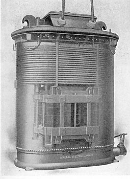
| Fig. 16. - Interior View of Necaxa Transformer. |
A vertical relief pipe 240 feet in height and 20 inches in diameter is connected to the upper end of each of the six pipes. It is interesting to note that these pipes are seamless steel tubesmade in Europe--with flanges, each piece being forged out complete from one piece of sheet steel. The outside diameter of the tubes is 30-5/8 inches throughout, with a variation inside from 0.4 to 0.95 inch, the minimum diameter being 29 inches. Before the flanges were hammered out two cast-steel clamping rings were slipped on to each 30-foot section of tube.
| |||
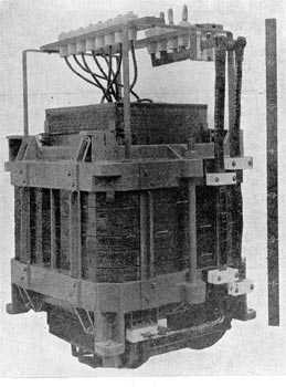
| Fig. 17. - Core of Necaxa Transformer. |
The initial apparatus in the main power station No. 7 has been furnished by the General Electric and Siemens-Schuckert Companies, and comprises six 5,000-kw, 4,000-volt, 50-cycle, three-phase, vertical shaft generators of Siemens-Halske construction. Each generator is driven by an impulse water wheel carrying 24 buckets at its periphery. The wheels (Fig. 7) are those of Escher, Wyss & Co., of Zurich, Switzerland. They are 100 inches pitch diameter,
 |
| Figs. 18 and 19. - General Plan and Cross-Section of Power House No. 1, Necaxa. |
