[Trade Journal]
Publication: National Electric Light Association Twenty-Sixth Convention; Papers, Reports and Discussions
New York, NY, United States
vol. 26, p. 24-28, col. 1
Mr. Martin's report was as follows:
REPORT OF THE COMMITTEE ON PROGRESS
·
·
HIGH-TENSION OVERHEAD TRANSMISSION
The recent development of high-tension long-distance transmission of current for purposes of electric light and power has naturally raised many practical questions of interest to central-station men. One of these is brought up in the mechanical specifications for a proposed standard insulator pin presented before the American Institute of Electrical Engineers last March by Mr. Ralph D. Mershon. The data are as follows:
Threaded End--It is proposed to make the diameter of the small end of the pin one inch; the length of the threaded portion is 2.5 inches, and the diameter at the lower end of the threaded portion 1.25 inches, so that the threaded portion will taper from 1.25 inches to one inch in a length of 2.5 inches. The threaded portion of the insulator should have the same dimensions and taper as that of the pin.
Shoulder--It is proposed to make the shoulder three-sixteenths inch on all pins. That is, the diameter of the pin just above the cross-arm will be three-eighths inch greater than the nominal diameter of that portion of the pin in the cross-arm. It is proposed to carry this diameter one-fourth inch above the cross-arm before tapering the pin.
Dimensions in Cross-arm--It is proposed to make the diameter of that portion of the pin in the cross-arm, just below the shoulder, one-thirty-second inch less than the diameter of the hole in the cross-arm and at the lower end of the pin one-sixteenth less than the diameter of the hole in the cross-arm. It is proposed, also, to designate this portion of the pin as having a nominal diameter equal to that of the hole in the cross-arm into which the pin fits. Therefore, that portion of a pin which is to fit a 1.5-inch hole in a cross-arm will have a nominal diameter just below the shoulder of one and fifteen-thirty-seconds inch, and at the lower end of the pin of seven-sixteenths inch.
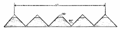 |
| Form of Pin Thread-High-Tension Overhead Transmission |
Thread--It is proposed to use on all pins a thread having a pitch of one-fourth inch, or four threads to the inch, the form of thread to be that shown in Figure 1 (scale four times full size). As there shown, the angle between the faces of the thread is 90, and the top of the thread is flattened by cutting off, from the form the thread would have if not flattened, one fourth its unflattened depth. The form of the thread in the insulator should be the same as that on the pin. If this is done it will insure the bearing surface being always on the sides of the threads and never on the edges.
Designation-- It is proposed to designate that portion of the pin above the cross-arm as the "stem" of the pin. That portion in the cross-arm as the "shank" of the pin. It is proposed to designate a pin by the length of its stem, i. e., a pin whose stem is five inches long will be designated as a "five-inch" pin, one six inches long as a "six-inch" pin, and so on.
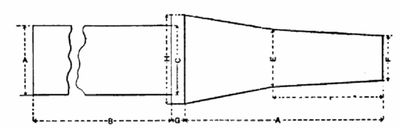 |
| Standard Pin-High-Tension Overhead Transmission |
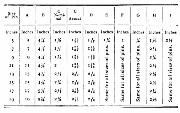
Dimensions of Standard Pins--In accordance with the above, the following table has been prepared, giving a number of sizes of pins and their dimensions, which it is proposed to make standard. The diameter of the shank has in each case been fixed by making it approximately equal to (slightly larger than) the diameter of the theoretical pin corresponding to the length of the stem of the pin in question. The headings of the columns of the table refer to the lettering of Figure 2. Figure 2 is a dimensioned unthreaded five-inch (proposed standard) pin.
 |
In this connection Mr. M. H. Gerry, Jr., of the Missouri River Power Company, favored a diameter greater than one inch at the top of the pin proposed and a thread greater than 2.5 inches. Prof. C. L. Corey noted Californian use of iron pins with porcelain sleeves on the 83-mile, 33,000-volt, 3-phase transmission line from the Santa Ana power house to Los Angeles. He described an iron pin designed by Mr. Wynne for the long lines of the Vancouver Power Company. It consists of a 12-inch steel bolt; a cast-iron sleeve 4.25 inches long fitting closely to the cross-arm filling the space between the thread and corresponding to the stem of the ordinary wooden pin. A lead thread is cast on the end of the steel bolt, which is first chopped or made ragged to enable the lead to hold. Mr. D. L. Huntington, of the Washington Power Company, Spokane, Wash., said that as the result of experiments a pin was adopted 18 inches long made of 1.125-inch round mild steel bar, with a shoulder and shank cast upon it. Mr. C. C. Chesney considered that the success secured in the operation of the great majority of transmission lines is due to the good insulation of the insulator, the insulation of the pin not entering; and that for 40,000 volts and higher, the insulators at present made do not have the same factor of safety as those for lower voltages offered by the same manufacturers. This difference is due more particularly to the general shape of the insulator and the dimensions of the insulating surfaces and petticoats. In localities subject to salt storms, heavy sea fogs or where there are chemical factories there has been more or less pin burning without regard to the type of insulator used or to the potential of the system. In one case, owing to deposit on insulators from a neighboring chemical factory, trouble was experienced from the burning of pins at 440 volts, though 10,000-volt insulators were used. The evidence, while not conclusive, points to the advisability of using iron pins with modern insulators properly chosen for the line potential. Mr. H. W. Buck said he had found many pins on the Niagara transmission line to Buffalo in which disintegration had taken place at the top of the pin. This would crumble into white powder which, when analyzed, was found to be a nitrate salt. This would appear to indicate that nitric acid was formed by the static discharge of the pin and had attacked the wood. He gave an account of an experimental 75,000 volt, single-phase line, the conductors of which were of iron tied with copper wires. At the end of five months the galvanized iron had turned black, although the iron guy-wires remained in their original bright condition, thus indicating that the blacking was not due to atmospheric conditions. It was noted that the wire became discolored on the surface to the depth of several thousandths of an inch, and the copper tie wire was also attacked to a certain depth, but not as much as the iron. This would appear to indicate that a nitrogen compound formed in a thin layer around the conductor at high voltage, due to brush discharges, and uniting with moisture, attacked the metal. It was also noted in the discussion that one of the newest lines in Mexico uses Portland cement and iron pins, set upon iron towers giving a distance between the insulators of from 420 to 500 feet.
·
·
