[Trade Journal]
Publication: National Electric Light Association Twenty-Eighth Convention; Papers, Reports and Discussions
New York, NY, United States
vol. 1, p. 213-233, col. 1
LONG-DISTANCE HIGH-TENSION TRANSMISSION IN CALIFORNIA
The state of California is entitled to the credit for initial, original and pioneer work in long-distance electrical transmission, not only in the actual operative length of lines, but also in the high pressures used in such transmission. The progress made by the financiers and engineers in this state, during the past ten years, has been so phenomenal as to attract world-wide attention, with the result that there is a constant stream, of those interested, from all parts of the world, to the Coast, to observe the original work being done. Not only is California concerned in its trials and triumphs in long-distance transmission, but it has been the pioneer in high-head hydraulic work, as developed for large units. A recitation of the developments of electric transmission in the state would occupy more time than your patience would admit of, but a brief resume of what has been accomplished in the past ten years, all now under the control of the California Gas and Electric Corporation, may not prove an uninteresting one.
In the year 1888, attention in the engineering world was attracted by the Folsom Water Power Company determining to build a dam across the American River, near the town of Folsom, and to erect a power house some two and one-half miles south of the dam- on the river, conveying water by a canal having a capacity of 40,000 miners' inches, to low-head turbine wheels, under a head of 65 feet. Four 750-kilowatt units were installed, generating current at 800 volts, stepping up to 10,000 volts, and conveying the current thus generated to the city of Sacramento, 22 miles distant. The promoters of this enterprise were discouraged by the inability at that time of engineers to guarantee that 10,000 volts could be safely carried that distance for commercial purposes. In 1895, this dream became a reality, and Sacramento city was supplied with current generated at Folsom. While the insulation provided gave more or less trouble initially, this was gradually overcome. In 1892, the late A. W. Decker, electrical engineer, acting for the San Antonio Light and Power Company, at Pomona, Cal., recommended the installation of electric equipment at the power plant of that company, to convey by means of step-up transformers a pressure of 10,000 volts over approximately 16 miles of line, to the city of Pomona. The generators as finally installed delivered single-phase current at a pressure of 500 volts, and the transformers were wound in the ratio of one to two. There were ten transformers in service on the primary, giving 10,000 volts with a capacity of 6 kilowatts each installed. Glass insulators were used upon this line.
 |
| Fig. IPower-Houses and Transmission Lines of the California Gas and Electric Corporation |
In 1895, there was begun the construction of a water-power plant near Nevada City, in Nevada County, in the state of California, to transmit about I 000 horse-power a distance of five miles, with generators wound direct for 5000 volts. The water was conveyed from a dam on the South Yuba River through three and one-half miles of flume, having a capacity of 8500 cubic feet per minute, and delivered to a 42-inch pipe, 286 feet long, with a head of 190 feet. There were installed at that time two 330-kw units.
From these small beginnings has grown a system throughout the state, aggregating in generator capacity at present installed, over 50,000 kilowatts, and units of 5000 kilowatts with varying heads up to 1530 feet. In the central part of the state, utilizing the waters of the western slope of the Sierra Nevada mountains, there are at the present time, in continuous operation, 577 miles of ditches, 25.5 miles of flumes, operating 14 water-power plants, having installed 41 generators, with a rated capacity of 50,790 kilowatts, and having a water storage in numerous lakes aggregating over 3000 million cubic feet, or 1,500,000 miners' inches for 24 hours. From these power-houses there are in continuous service 715 miles of pole line and 734 miles of circuit operated at 50,000 to 60,000 volts, and 479 miles of circuit at voltages varying from 10,000 to 50,000, and 90 miles at lesser voltages, not including any local distribution. Power is delivered to 94 substations, with 75,000 kilowatts in transformer capacity installed, scattered over 21 counties and 33 cities in the state, representing a population of over 6o per cent of the entire state of California, and covering an area of 15,000 square miles. This power is regularly transmitted 232 miles, and by reason of certain conditions at times existing at the different power plants necessitating the transmission over all lines from one power plant, has been successfully operated 325 miles at 55,000 volts.
In addition to the transmission of power, as heretofore and hereafter enumerated, it may be interesting to know that the high-pressure wires supply 1961 miles of distribution wires in service, from 2300 to 5000 volts, and serve approximately 20,000 consumers for lighting, and motors of 100 horse-power and less, totaling 40,000 horse-power.
As the writer has been requested to confine his statements particularly to the subject of high-tension work, and, in a general way, avoid all technical descriptions, avoidance will be made of unnecessary details of power-house operation, or of the operation of the hydraulic systems in connection therewith, and only so far as it may be necessary to illustrate a point made, this paper will be concerned solely with the transmission lines.
In no other portion of the globe where long-distance transmission under extreme high potential has been used, do climatic conditions exist similar to those in California, and this must be particularly borne in mind when considering the work that has been done, the problems solved, and the successful conclusions arrived at in the determination that there is no limit, except that of the earning capacity on capital, to the carrying of current over wires to any distance.
As above stated, power is obtained from the waters flowing from the west slope of the Sierra Nevada mountains. These mountains are snow-capped the year round, and some of the power-houses are within the snow belt which exists during the winter season. Following down the mountain sides, these pole lines emerge into the vast Sacramento and San Joaquin valleys, which extend from Sierra County on the north to Kern County on the south, a distance of approximately 350 miles, and will average about 6o miles in width. After leaving the valleys, the pole lines cross the Coast Range, lying between the valleys and the Pacific Ocean, and generally follow the contour of the bays of San Francisco, San Pablo and Suisun, until they reach the commercial centres of distribution. In this long distance traversed, they are subjected to extreme climatic conditionsfrom the colds and frosts of the mountains to the severe heat of the valleys, and to the cooling fog-laden winds from the ocean.
The first transmission line to reach the bay shore was that of the Bay Counties Power Company, carrying current generated at Colgate on the Yuba River, about 28 miles northeast of the city of Marysville. This line was started at 44,000 volts, which voltage has since been raised to 55,000. The construction of the line was of round cedar poles, from the state of Oregon, an average height of 5o feet, and the character of construction substantially that now in use, but with a less separation in some instances than was subsequently found necessary. The very many alterations of plans from time to time, as different conditions obtained, to insure service, need not be here recapitulated, the details being confined to present method of construction, as will be illustrated by photographs and cuts annexed. The greatest difficulty encountered in the carrying of the high potential was in and about the bays mentioned, due to the heavy salt fogs that for certain periods of the year hang densely over the land, sometimes lasting for days. In these particular districts, the insulation has broken down at most unexpected places, causing the burning off of poles, and shortening the line. The new four-part insulator herewith illustrated, with iron pins, has entirely overcome this defect, and for the past season, under the most trying circumstances, no trouble has occurred, the number of hours of shut-downs upon all of these lines being of a negligible quantity.
In addition to the conditions named of transmission over and through countries of varying temperatures, it must be remembered that for seven months of the year, extending usually from April until the first of November, no rain falls within the district named, and where the pole lines run along or adjacent to the public highways, where heavy teaming for all purposes is carried on, they are covered with a fine dust, which arises from traffic, and are subjected at times to extremely hot north winds. For the remaining five months of the year the lines are subjected from time to time to heavy rains and to the high winds accompanying the winter storms. Bearing all these facts in mind, it is nothing short of remarkable that within a period of not over four years such wonderful results have been obtained in transmitting current over the distances involved; for the establishment of the Colgate plant, and the carrying of current into the city of Oakland, its initial distributing point, occurred in the year of 1901.
 |
| Fig. 2Crossing of Carquinez Straits |
One of the greatest engineering feats ever accomplished, and one that has never received from the engineering world the attention which it deserves, was the construction, in 1901, of the famous Carquinez span of four steel cables, suspended from steel towers (see Figure 2). This span crosses the Carquinez Straits, connecting San Pablo and Suisun bays, and is 4427 feet in length between towers, having at its maximum point of dip an elevation of 206 feet above high-water line. The maximum sag of the wire between the two steel towers on the north and south sides of the straits is 257 feet. The main tower, in Solano County, on the north side of the straits, is 224 feet in height, and the bluff at the point of construction is 162 feet above tide water; on the south side the tower is 64 feet in height, and the bluff 400 feet above tide water. The accompanying sketch will convey a very accurate description of this span. It is interesting to note that this crossing has given absolutely no trouble in operation. Both of the towers mentioned are used for distributing stations to the different manufacturing cities along the bay shore, besides serving as general switching stations.
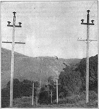
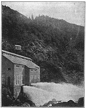
In the ordinary construction, spans up to 1800 feet in length are constructed in the mountains across deep ravines, using ordinary 40-foot round cedar poles for this purpose. A good sample of this work is shown in the photograph attached, in connection with the spans from the de Sabla plant to the Valley Counties Power Company, in Butte County.
Experience has demonstrated that the form of lightning arrester which gives good service at low voltage is absolutely useless on high-tension lines. While these were first installed, they have since in every case been abandoned. At the present time nothing is used but the Horn Gap arrester. As the voltage of the lines has been raised, and the insulation increased, the damage due to lightning is steadily decreasing. It is well to state that beyond the line of the foot-hills of the Sierra Nevada mountains, lightning rarely occurs; possibly once a year throughout the Sacramento and San Joaquin valleys and along the bay shore are there any discharges of lightning that would be detrimental to the lines.
 |
| Fig. 3 and 4Illustration of 60,000-Volt Insulators |
The first construction of lines in this state was 40 to 50 poles to the mile, insulators being used at a maximum cost of 15 cents.
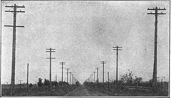
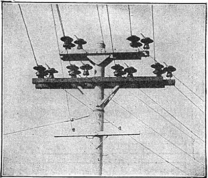
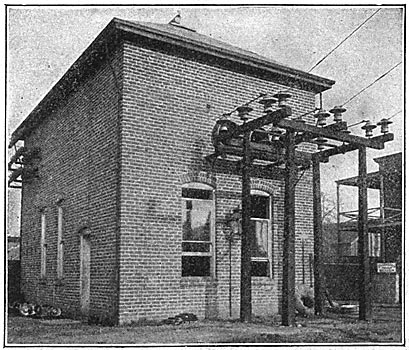
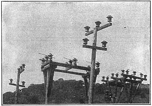
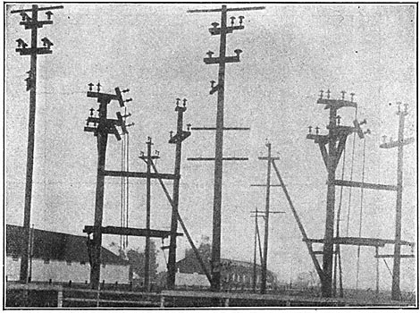
All new lines are now being constructed on the basis of 20 poles to the mile, and the four-part insulators illustrated in Figures 3 and 4 are being used, costing approximately $2.00 each, and weighing about 30 pounds. These are the outcome of months of patient work and experiment by the engineers on the Pacific coast. Figure 5 exhibits graphically the character of construction of pole lines about six years ago, and the ravine illustrated in that picture is now crossed with a single span. Figure 6 shows the general construction of the pole top for 60,000 volts. Figure 7 shows the transmission line from the Folsom plant, heretofore mentioned operating to-clay as when it started, with four circuits at 10,000 volts at over 18 per cent loss. These circuits are now being changed to operate at 60,000 volts, and the type of construction As shown in Figure 6, and the loss in the 22 miles of transmission at 60,000 volts, with only one circuit, will be about 2 per cent. Figure 8 illustrates the method of construction at corners, giving a view of the insulated guards attached to the outward insulators to prevent wires from falling to the ground if pulled over. This has proved effective in more than one instance. The construction shown is at the top of a 6o-foot round cedar pole. Attention is particularly called to the very strong methods adopted in both cross-arm work and braces.
| |||
| Fig. 5Illustrates Old Method of Crossing Ravines. Present Construction in Same Place Spanned by One Pole |
 |
| Fig. 6Present Method of Constructing Pole Tops for 60,000 Volts. |
| |||
| Fig. 710,000-Volt Line From Folsom Power-House (Old Construction) |
| |||
| Fig. 8Pole Top, With Guards on Corner |
 |
| Fig. 960,000-Volt Outdoor Line Switch |
| |||
| Fig. 10Outdoor Disconnecting Switch |
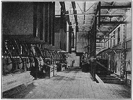
Much work has been done in designing and carrying out the construction of outdoor switches, as shown in Figure 9; and Figures 10 and 11 will show the switches in place, arranged for three-pole remote-control operation. Figure 12 is a record of the past, and exhibits some of the earlier attempts at a line disconnecting switch. Experiments have been continuous along the lines of oil switches, and experience has demonstrated sufficiently that this switch as at present constructed is entirely satisfactory and will handle heavy currents under high pressures. Double-break and quadruple-break oil switches are now being made, the latter being used for very heavy service in the large power-houses. Figure 13 shows one form of oil switch, and also shows the method of constructing fireproof switch galleries, the construction of which, so far as the writer is advised, is entirely original with the Pacific coast. The switching is done by opening the three legs at the same time, the single-pole arrangement having been found to be extremely unsatisfactory for obvious reasons. Figure 14 will illustrate a switch for disconnecting a bank of transformers from the bus-bars. Figure 15 will illustrate the past methods of construction of switches and transformers for high-pressure wires, while Figure 16 illustrates the present method, not only of the fireproof switch galleries, but of modern construction of a powerhouse, showing location of water-wheel, generator, exciter and switchboard. Figures 17 and 18 illustrate the present method of switching arrangements at substations for connecting and disconnecting lines.
| |||
| Fig. 11Outdoor Switch |
| |||
| Fig. 12Old Method of Line Disconnection |
 |
| Fig. 1360,000-Volt Double-Break Oil Switch |
 |
| Fig. 1460,000-Volt Disconnecting Oil Switch |
As evidencing the care exercised in protecting low-tension circuits from high-pressure wires where the low-tension parallels the high-tension, in the event that there should be any fall to the ground of the insulation of the high tension, Figure 19 is fully illustrative.
| |||
| Fig. 15Old Arrangement of Switches and Transformers |
 |
| Fig. 16New Arrangement of Fireproof Switch Galleries, Etc. |
 |
| Fig. 17Disconnecting Switches |
 |
| Fig. 18Disconnecting Switches |
Referring to chart Figure 17, this station is midway between Colgate plant, heretofore referred to, and the city of Oakland, on the bay shore. Each line shown represents a three-phase circuit, the large circles representing oil switches. Disconnecting switches are shown on each side of the oil switches. At the station represented in Figure 18 there is no regular operator, and therefore in regular operation switches one and three are closed, and when necessary to open the line, switches Nos. 2, 4 and 5 are closed; then No. 3 or No. 1 opened, and then the oil switch No. 6, which opens the line.
 |
| Fig. 19Protection of Distributing Lines |
| |||
| Fig. 20Hauling Armature |
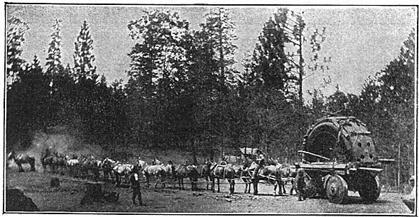
In addition to the illustrations heretofore referred to, the difficulties attendant upon conveying material to the power-houses will be noted in Figure 20, and an illustration of hauling the upper part of an armature of a 5000-kw generator to one of the mountain power-houses. Thirty-six horses were required to pull this machine over six miles of mountain road, from railroad to head of pipe line, and the descent from the penstock down the mountain side to the power-house, over four miles of the roadway, having a grade of approximately 10 per cent, was attended with more or less dangers.
Other than the line heretofore mentioned, conveying power from Colgate to the Bay of San Francisco, the line of the Standard Electric Company to the power plant at Electra, on the Mokelumne River, a distance of 142 miles from San Francisco, is an illustration of the possibilities of the increase of the efficiency of the line by high insulation. When first constructed, this line was operated at 33,000 volts, which potential was maintained until March, 1904, when steps were taken to operate it in parallel with the other lines controlled by the California Gas and Electric Corporation, the Bay Counties and the Valley Counties companies, and it was at that time increased to 55,000, and has been so operated ever since. The type of insulators in use in March, 1904, has been substituted for the four-part type illustrated, in such sections of the territory of the Standard as by reason of climatic conditions called for a higher insulation.
Outside of the immediate fog belt mentioned, the two and three-part types of insulators have been found extremely efficient for voltages up to 60,000, and experiments have been made to demonstrate that they will safely carry 80,000 volts without breaking down.
 |
| Fig. 21Illustration of Power-House Areas |
The progress made in the engineering and construction work of power-houses has kept pace with the progress in pole-line work, and insulating and switching devices. The chart herewith, Figure 21, giving the areas of power-houses, graphically shows the contraction of areas in the installation of large units, as it follows closely in the line of distributing stations, where, as can be remembered, the belted units for alternating-current work have increased from 35 kilowatts to the large direct-connected units now in vogue, in some cases as high as 12,000 kilowatts. The first installation made at Electra, in 1899, of five 2000-kw units, called for a floor space equal to 1.16 square feet per kilowatt; the Colgate installation made in 1897, of 9400 kilowatts, called for 0.98 square foot per kilowatt; the recent installation at the de Sabla powerhouse of the Valley Counties Power Company, of 9000 kilowatts, called for but 0.4 square foot per kilowatt. The installation now being made at Electra of two 5000-kw units, calls for but 0.288 square foot per kilowatt. The areas given include room for transformers, switches, and so forth.
It will be noted that the first installation at Electra required four times the floor space per kilowatt as compared with the work at present being done, and illustrates more clearly than words can convey the advancement in the past six years. It is believed that the floor area in the new Electra installation is less than that of any other power plant in existence to-day. In these plants there is no crowding of apparatus, and there is ample room for all operation or repairs, and in future work it will be safe to assume that this minimum of floor space can be still further reduced. Reduced floor area means, of course, reduced operating expenses, as well as reduced cost of construction.
| |||
| Fig. 22De Sabla Power-House, Showing Long Spans on 40-Foot Poles, Crossing Mountain Ravines |
When it is considered that the operation of these power plants extends to an infinity of uses, from the moving of street cars to the operation of sewing machines, from factories using ponderous machinery and exacting conditions of demand to the most minute uses to which electricity can be applied, and that during the four years of active operation on this coast new contracts are continually being made for the use of electricity against the installation of steam plants that might be operated with the cheapest fuel known (which is California oil at between 55 and 60 cents per barrel of 42 gallons), it is a tribute to the knowledge, perseverance and energy of the engineers that such work has been accomplished and so perfectly done in so short a space of time. Motors as large as Boo horse-power come on and off the line unnoticed.
From the point in the mountain stream where the diverting clam arrests the onward flow of the water through the ditches constructed upon the sides of the chasms, the flumes across deep canyons, to the utilization of such water at the water-wheel, and then over the lines by which the invisible current is conveyed over the many miles of copper and aluminum wires to points of distribution, there is exercised a watchfulness and care that is unceasing. Constant lines of patrol are maintained at the reservoirs, on the flumes and ditches, and along the pole lines, and direct telephone connection is made by the patrolmen, over private telephone lines, to the central power-houses. By the construction of the double-pole line from the main power-houses to the bay, constant service is insured, because it is but the work of a moment to switch the high potentials, by means of the switches illustrated, from one line to the other.
Experience with aluminum wire along the bay shores has demonstrated that it is impervious to the action of the atmosphere heavily laden with salt, and quite as effective in that regard as the copper.
THE PRESIDENT: We will now take up the report, Present Methods of Protection from Lightning and Other Static Disturbances, by Messrs. Alex Dow and Robert S. Stewart, of Detroit. Mich. Mr. Dow will present the report.
