[Trade Journal]
Publication: Transactions of the American Society of Civil Engineers
New York, NY, United States
p. 380-388
PROGRESS IN TRANSMISSION.
As regards transmission of continuous current used for lighting and general power purposes, underground circuits in large cities of the United States and in many important towns of less size have, in very large degree, displaced overhead circuits. Improvement in quality and reduction in cost of insulated lead-sheathed cables have resulted from the competitive efforts of many manufacturers in America and Europe, and these improvements, in connection with the development of higher aesthetic standards in urban communities, have resulted in a gratifying reduction of the amount of overhead construction in this class of service. In connection with continuous-current distribution for the operation of electric street-car service, relatively less progress in substituting underground for overhead construction has been made, but in some of the most important cities, notably in Washington and in the Borough of Manhattan, City of New York, the greater part or all of the street-car service is supplied without any overhead construction whatever. In a number of cities, while the overhead-trolley wire is used, the feeder circuits in whole or in part have been placed underground.
 |
| Fig. 1. |
Transmission by alternating currents has undergone remarkable development in the last ten years. Power to the amount of 10,000 kw., developed by mountain streams, is transmitted to cities and towns in California located at distances ranging from 154 to 218 miles from the generating stations. These plants use 40,000 volts for the transmitting circuits. Buffalo is supplied with more than 18,000 kw. from Niagara Falls. Montreal is receiving power from the Shawinigan Falls over circuits 85 miles in length, operating at 50,000 volts, and the plant of the Guanajuato Power Company in Mexico is successfully delivering power over circuits 101 miles in length, and operating at 60,000 volts.
Transmission plants which ten years ago would have been regarded as remarkable now attract little or no attention as they are successively placed in commercial operation. Lists of alternating-current transmission plants recently furnished by the three leading American companies manufacturing this class of apparatus, show that they have installed in the United States, Canada and Mexico, 447 plants, aggregating 734,123-kw. output. The potentials range from 125 to 60,000 volts, and the distances of transmission vary from a few feet to 218 miles. The limits of this paper forbid even brief reference to very many points of interest; only a few of the more salient and important facts can be mentioned.
The highest potential in commercial use is 60,000 volts; the longest distance over which power is electrically transmitted is 218 miles. The largest copper conductors used in America for overhead transmission at a potential exceeding 20,000 volts are of 350,000 cir. mils. section, and the largest aluminum conductors similarly used are of 500,000 cir. mils. section.
An idea of the range and efficiency of electric transmission, using potentials now in commercial use, conductors of sizes now in commercial use and transmitting power to the maximum distance thus far attained in commercial operation, may be conveyed by the statement that at 60,000 volts a three-conductor circuit comprising three copper conductors of 350,000 cir. mils. each will transmit 7,500 kw. (10,000 e.h.p.) a distance of 218 miles with a loss in the transmitting circuits which, making due allowance for the wattless component of the current, will not exceed 10 per cent.
Improvements in the art of transmission effected by changes of the systems used—the introduction of the alternating-current system sometimes as successor to the continuous-current system, sometimes in combination with the latter to increase the radius of transmission—have been referred to previously in this paper. It remains now to note, and necessarily very briefly, improvements in respect to certain specific apparatus used in electric transmission, and it may be well to consider (1) certain apparatus used in transmission by overhead circuits; (2) apparatus used in transmission by underground circuits; and (3) apparatus common to both overhead and underground transmission.
Overhead Transmission.
In the art of transmission by overhead circuits, advance may be noted particularly in respect to insulators, lightning arresters, and in the use of steel towers instead of poles.
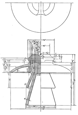
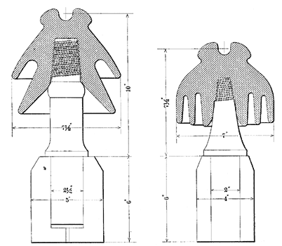
Insulators.—The dimensions and form of the insulator used for the 60,000-volt transmission at Guanajuato are shown in Fig. 1, and for purposes of comparison the so-called Type C insulator used in the Niagara-Buffalo transmission in 1896 is shown in Fig. 3. As representing an intermediate step in development, Fig. 2 shows the dimensions of the Type E insulator used in the construction of the second Niagara-Buffalo Line constructed in 1900. Type C and Type E insulators are porcelain, and are moulded and fired as single pieces. The Guanajuato insulator is porcelain, but is built up of pieces which are moulded and fired separately, and subsequently assembled and held together by a special cement or glaze. Manufacturers of porcelain find it extremely difficult to produce single-piece insulators of dimensions materially greater than those of Type E, owing chiefly to the fact that as dimensions increase, differences between maximum and' minimum thicknesses of the porcelain necessarily increase, and it becomes almost impossible to fire properly and uniformly all parts of the insulator. In cooling, moreover, the differences in thickness tend to cause shrinkage cracks, weaken the insulator and cause it to break readily under test or subsequently in service. For very large insulators, therefore, best results are attained by composite construction, as illustrated in the Guanajuato insulator, since by this method of manufacture the difficulties resulting from difference in thickness and rate of cooling are in great measure avoided. American porcelain, although much improved during the-last decade, is not yet equal to the best grades used in Europe in the construction of insulators.
 |
| Fig. 2 — Fig. 3 |
Line insulators obviously must be designed to resist puncture by high potential which tends to strike through from the conductor to the pin, and also to prevent the establishment of a circuit from the conductor across the surfaces of the insulator. Improvement in quality of the material used implies, to some extent, the possibility of using higher potential with given thickness of porcelain between conductor and pin, but the greatest gain that has been made is in the approach to perfect homogeneity of the porcelain.
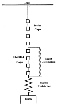
Lightning Arresters.—The protection of overhead transmission circuits against lightning has received much attention from investigators and inventors since dynamic electricity was first used to transmit energy. In the earliest days of alternating-current development in America, arresters of a type which had been used' with considerable success for the protection of apparatus used in telegraph service, were tried, but more than ten years ago their utter futility in protecting constant potential circuits supplied by dynamos of large power had been demonstrated. Several interesting types of arresters had been proposed and more or less experience acquired in their use. Among these, Elihu Thompson's magnetic blow-out arrester had proved its effectiveness in protecting continuous-current constant potential circuits such as are used in supplying continuous-current series arc-lamp systems. This arrester is still in very extensive use and is generally regarded as effective and satisfactory. For the protection of constant potential alternating-current circuits, which class comprises practically all long-distance transmissions, the so-called "non-arcing metal" arrester discovered by Wurts was beginning to demonstrate its fitness to survive the majority if not all of its rivals. Attached to this class of circuits, the arrester must perform the double function of preventing abnormal rise of line potential and suppressing the arc which tends to form across the air gap when the discharge passes to earth. Fig. 4 illustrates the essential parts of one of the latest forms of arrester in which non-arcing metal is used. Seven brass cylinders, each approximately 3 in. in length and 1 in. in diameter, are mounted parallel to each other, separated by air gaps approximating A in. A moderate resistance is connected in series with the cylinders and between them and earth, while a higher resistance is connected in shunt around three of the gaps. The number and width of the series gaps are adjusted for a reasonable factor of safety with reference to line potential with one line of the circuit grounded. The shunted gaps provide a path for the lightning discharge, which, if of any considerable quantity, is unable to pass through the shunt resistance without dangerous rise of potential on the line. The shunt resistance helps to suppress the arc across the shunted gaps, and after the passage of the discharge and when the arc across these gaps is suppressed, it limits the current across the series gaps and so assists in the final suppression of the momentary discharge.
 |
| Fig. 4. |
In the best American practice in protecting high potential alternating-current transmission circuits, paths to earth are provided by several arresters connected to each line of the circuit, and between each two successive points at which the arresters are connected to the line a reactance coil is introduced in the line circuit to aid in preventing the lightning discharge reaching transformers or dynamos, and compelling the discharge to go to earth across the air gaps provided for the purpose. Of course where the line potential exceeds 6,000 volts, the number of cylinders and air gaps and the proportions of the shunt and series resistances are increased.
Use of Steel Towers.—The plant of the Guanajuato Power. Company not only uses higher potential than had been adopted previously in commercial service, but the construction of its transmission circuits marks an important step in progress by the substitution of steel towers for wood poles, and the use of an average span of 440 ft. instead of the usual shorter spans, which range from 70 ft. to approximately double that distance. The plant has been in operation for nearly a year and is said to have operated during this period with entire success. The towers used are of galvanized steel and are similar in general design and construction to the towers commonly used in America for windmills. Taking into account the cost of cross-arms and insulators, a line thus constructed should be, in general, no more expensive than the ordinary wood-pole line while, properly designed, it is of course far superior with respect. to durability and appearance. Some engineers oppose the use of steel poles or towers in connection with iron cross-arms and insulator pins on the ground that to substitute for wood in the construction of pins and cross-arms a material of high electrical conductivity is ill-advised because it reduces the insulation of the circuits. Undoubtedly it tends in this direction, but the experience of the Guanajuato Power Company seems to demonstrate that insulators, which may be depended upon to secure effective electrical separation of the several wires of the circuit, are now available, and from a mechanical viewpoint the steel tower seems so far superior to the wood pole that its speedy general adoption in transmission installations of importance may be hoped for. In Europe it may be noted that steel poles have been used for a number of years in some of the more important transmission installations, notably that between Paderno and Milan, in which the potential used is 13,000 volts, the distance of transmission being approximately 35 miles.
It is appropriate to mention here the daring and successful tower construction used by the engineers who designed the transmission circuit which crosses an arm of the bay near San Francisco. In this case, the span is 4,227 ft., the conductors being steel cables 7/8 in. in diameter; three of these conductors are carried by steel towers. The tower on the north side of the bay is 225 ft. in height, while the tower on the south side is 65 ft. in height. The design and construction of the insulating saddles, which perform the double function of insulating these cables against working potential of 40,000 volts and of mechanically supporting so long a span, are notable engineering achievements.
