[Trade Journal]
Publication: Electricity at the Columbian Exhibition
Chicago, IL, United States
p. 205-208, col. 1
SUBWAYS FOR ELECTRIC WIRES USED AT THE COLUMBIAN EXPOSITION.
When plans were first formulated for the lighting of the grounds of the World's Columbian Exposition, it was decided that all electric wires and conductors, not only for arc and incandescent lighting, but for power transmission, police signals, fire alarm, telephones and telegraph lines should be placed underground out of danger to the public and yet be accessible. For this purpose the electric subway was designed and constructed. The original plan was to build such a subway of solid brick, but as this was found unnecessary for temporary service, and expensive, the plans were changed to a wooden frame-work lined with cement, plaster and with concrete floors. The plans that were approved and executed called for a subway to connect the electrical plant in Machinery Hall with Mines and Mining, Electricity, Manufactures, Government and Fisheries buildings. The main subway starting from Machinery Hall was 15 ft. 8 in. wide by 8 ft. 4 in. high and was divided in the center by a fireproof partition, making two divisions 6 ft. 6 in. square on the insides. This subway was run to within 50 feet of Electricity building where, from the west division, extended two branches 8 ft. 4 in. high by 6 ft. 1 in. broadone to Mines and Mining and the other to the Electricity building. These were so arranged that all the wires on the west wall turned west to Mines and Mining, and those on the east wall were run directly into the Electricity building without crossing. The east division at the 50 foot point turned east to the bridge at the southwest corner of Manufactures building, where it widened out into a fan shape the width of the bridge and the wires were carried across on supports placed between the bridge girders. From the bridge the subway extended 100 feet east to the west loggia of Manufactures building where it turned north, going the entire length of the building, but as all the wires on the east wall turned into the building at branches placed near the southwest corner and center, the size of the subway changed just north of the west center to a section the same size as the branch to the Mines and Mining building. At the northwest corner of the Manufactures building the subway turned east to the north center, where it again changed to a section 5 ft. 9 in. wide by 6 ft. high, reducing the capacity by one-third. From this point it turned north, running under the Government building and across the north inlet bridge to the Fisheries building, where the subway ended. In Machinery Hall there was a large double subway commencing opposite the Thomson-Houston switchboard of the power plant, and running 825 feet east under the south aisle, where it connected at the east entrance with the main subway and at the west end with a duct trunk line. The general construction of all the subways consisted of a framework of 3 inch by 8 inch material placed 1 foot centers, and covered on top, bottom and sides with 2 inch matched planking. The inside was lined with standard metal lath and Acme cement mortar on top and sides, the bottom being covered with 4 inches of sand and 6 inches of concrete. The cross section of the main subway at Machinery Hall showed two bodies of wires in each of the two divisions, supported by arms projecting from the wall. These cross-arms, twelve in number, two feet two inches long, were held in position by cast iron uprights, lagged to the frame work of the subway. Each cross arm supported five pins and insulators, making a total capacity of 240 insulators in a cross section. These uprights were placed at distances of about 30 feet apart through the entire subway and consisted of six different types, known as types 4, 6, S, 8 a, 12 and 12 a; the number indicating the number of cross arms each supported. Types 8 and 8 a, 12 and 12 a, were used ingoing around the corners. The cross arms projected into the subway 2 ft. 2 in. from either side, giving a clear passageway of 2 feet in the center. In all there were about 6,000 cross arms and 30,000 pins in use throughout the subway. For access to the subway and for convenience in pulling in wires, manholes were placed at distances of about 150 feet apart. These consisted of a round cast-iron box 20 in. in diameter and 20 in. high, resting on the framework of the subway and supplied with a cast-iron cover. The first contract, which called for the construction of the main part of the subway, was awarded January 23rd, 1892, to T. C. Brooks & Co., of Jackson, Michigan, for the sum of $35,094.49. Work was begun the first day of February, 1892, and was to have been completed by April 15th, 1892, but owing to frozen ground and rainy weather it was greatly delayed. The bottom of the subway being only a little above datum, considerable difficulty was experienced in putting in the concrete and flooring on account of water, but this was overcome by the use of an electrical portable pump. This contract did not include the subway running east and west under Machinery Hall, the portion under Government building, the branches under Manufactures nor the bridge approaches. This latter work was done by the Exposition Company, except the plastering on the subway under the Government building, which was done by Wm. Pickland & Co., for the sum of $1,010.00. The east and west subway under Machinery Hall was put in under many difficulties, chiefly because of necessity to follow the building aisles and on account of steam and water pipes. The total length of subway, including east and west subway under Machinery Hall, all the branches and approaches to the bridges, was 6,195 feet. Wiring of the subway was begun in the middle of February, 1893, and continued for about six weeks. It was found that there were so many arc wires for Manufactures building which had to be placed on the east wall of the east subway that it was necessary to run two wires on one insulator, and for that purpose a special two-wire insulator was designed giving a perfect glass insulation between the two wires. Wires were also arranged so that no two wires of different potential would come on the same insulator. The wiring of the subway required 4,000 of the special two-wire insulators and 20,000 of the regular single glass insulators. The subway contained 25 2-10 miles of power, 28 7-10 miles of incandescent and 51 miles of arc wires, making a total of 104 5-10 miles of wire for lighting and power transmission. Besides these, were telephone and telegraph cables, fire alarm and police signal wires.
| |||
| Subway Used at the Exposition. |
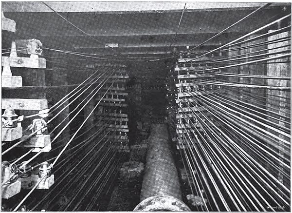
For the convenience of drainage the profile of the floor of the subway was so arranged that all water which might collect would flow to four points, namely, north of Machinery Hall, south of the Electricity building, west end of north railroad bridge and north center of Manufactures building. At the bridge, an opening was made into the lagoon so the water would flow out, but at the other three places marine pumps were installed and the water pumped to the nearest catch basin. In this way the subway was kept comparatively dry except on one or two occasions when a water pipe burst, completely flooding everything. The subway was lighted with 225 110-volt 16-c.p. Edison incandescent lamps placed at distances of about 30 feet apart throughout the entire length. The lamps were placed five in series and supplied with current from the 500 volt power circuit. The lamps of different circuits alternated in location so that in case one lamp burned out it did not leave the subway in total darkness. For the convenience of keeping an exact record of the position of every wire throughout the entire course of the subway, a system of card cataloguing was arranged. The cards were printed showing the exact position of all the cross arms and insulators supported by one set of uprights. Each insulator on a cross arm was numbered and each cross arm was also numbered. On each card was marked the position of the wire on the insulator, and the circuit number of every wire, at any given point of uprights. The uprights also all being numbered a card was made out for every set of cross arms and arranged consecutively in a file. By this means it was always possible to tell the exact position of any wire at any point in the subway. Wires which ran north from the Fisheries building were carried from the subway into a duct trunk line which ran east to the Intramural railroad and thence north, following the line of the road around the Montana State building. This trunk line was 2,250 feet long and contained 15,270 feet of pump logs. A clause in the contract of the Intramural railroad reserved the right for the Exposition Company to carry light and power lines along the structure underneath the road-bed, on extension insulators, and lines were run in this way wherever they were desired along the route of the road.
