[Trade Journal]
Publication: Electric Telegraphy
New York, NY, United States
p. 147-159
CHAPTER VIII.
LINE CONSTRUCTION.
TELEGRAPH wires in the open country are always bare copper or iron conductors supported on insulators from pole cross arms. When crossing rivers, and in the streets of large cities, cables of insulated wires are frequently employed, while in crossing oceans, insulated wires are, of course, rendered necessary. Until recent times, galvanized iron wire, usually 0.165" in diameter, was almost universally used, but lately, hard-drawn copper wire has largely replaced iron, owing to its advantage in conducting power.
In discussing line construction it will be convenient to commence with the insulator on which the wire is supported, then the pin on which the insulator rests, then the cross arms which support the pin, and finally the pole to which the cross arm is attached.
Insulators are almost invariably made of glass, a material of very high insulating properties. An insulator consists of an inverted cup upon the external surface of which runs a groove in which the wire is secured, while a thread is formed on the inside of the cup to receive the insulator pin.
Two common forms of insulator are shown in Fig. 56. They differ only in details of form, one having a deeper groove in its surface and being called a deep-groove insulator. The other more nearly resembles a bell in shape and is usually called the Western Union insulator. The thread for the pin cast in the interior is visible through the glass.
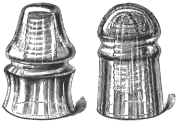 |
| Fig. 56.—Forms of Glass Insulators. |
Fig. 57, shows another form of insulator, partly in section. It will be seen that it has a double petticoat, the second one within the first. The object of this is to provide a longer path between the wire on the external surface and the pin in the internal thread. In all cases the leakage which occurs at an insulator from the conducting wire to the ground takes place almost entirely over the surface of the insulator and not through its substance. In damp weather, a film of moisture is readily deposited on the surface of the glass.
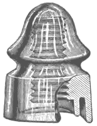 |
| Fig. 57.—Double Petticoat Deep-Groove Insulator. |
This film affords a partially conducting track over which the electric current may escape from the wire, especially if, as usually happens, the surface of the insulator is dusty, so that the film, instead of consisting of pure water which is almost an insulator, consists of muddy or sooty water which is a comparatively good conductor. The greater the length and the narrower this partially conducting film, the greater will be its resistance and hence the smaller the amount of leakage it will permit for a given voltage on the line. An additional petticoat placed within the insulator lengthens the film of surface and improves the insulation.
While the effect of moisture is to cause increased leakage over a telegraphic circuit, yet, to a certain extent, it is desirable that insulators be placed where they are freely exposed to the rain, since they are thus cleansed on their external surface from dust and dirt which otherwise would continue to accumulate upon it. For this reason, it is undesirable to place insulators under covers of any kind.
Since there are about 40 poles to the mile of ordinary telegraph line there are 40 insulators, and, consequently, 40 independent points where leakage may occur. In a line 10 miles long, there will be say 400 poles, and in a line 100 miles, 4,000; consequently, as we have already seen, the leakage increases with the length of line, so that the degree of insulation which would be fatally low upon a long line becomes a matter of indifference on a very short one.
The insulation of telegraph lines varies greatly with the weather and the locality. In fine, dry weather, the insulation may be several millions of ohms per mile, that is to say, the resistance between the wire and ground in the length of one mile may average several millions of ohms. In very wet weather the insulation may only be about one hundred thousand ohms per mile, assuming of course that the insulators are all properly set, and that the wire does not pass through trees. Where wires come in contact with the cross-arms or wet leaves, the leakage may be much greater, so that the insulation in wet weather may fall to only a few thousand ohms per mile. Near the sea, or over salt marshes, the insulators are apt to become coated with a film of salt, and in this way the leakage over them may be comparatively great. Consequently, lines running near the sea frequently have a lower insulation than those which run over dry plains in the interior.
In Europe, where the climate is generally much more moist than in the interior of the United States, glass insulators are never used. Owing to the hygroscopic qualities of glass and its tendency to retain a superficial film of moisture, glazed porcelain or glazed earthenware is invariably employed and in a great variety of forms. In a few instances oil insulators are used, that is to say, the insulator forms a cup for the reception of oil. This prevents any continuous film of moisture being formed between the pin and the external wire, and such insulators, if periodically emptied and refilled, have a very high insulation.
A number of European insulators are illustrated in Fig. 58. Here the single and double petticoat types are represented in various forms. A and B, are oil insulators. Porcelain insulators are occasionally used on the seacoast in the United States. Although they offer a better degree of insulation for the wire they are decidedly more expensive than glass insulators.
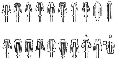 |
| Fig. 58.—Forms of Insulators. |
The insulators are screwed to pins which are either supported on a cross arm, or against a flat surface, such as the trunk of a tree or the side of a pole. Both of these forms and their mode of attachment are shown in Figs. 59 and 60. A, Fig. 59, is the usual pin which fits into the cross-arm, being secured in place in the latter by a transversely driven nail. B, is a bracket pin; C, is a double or duplex pin for supporting two insulators, one at each end.
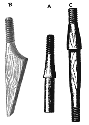 |
| Fig 59.—Insulator Pins. |
This is often employed where two wires are led off at right angles. These duplex pins are represented in a cross arm in Fig. 61, together with a duplex bracket. Pins and brackets are usually made of oak or locust, but any tough wood will answer for the purpose.
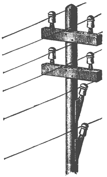 |
| Fig. 60.—Bracket and Pin Attachments. |
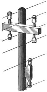 |
| Fig. 61.—Duplex Pins and Bracket. |
Cross arms are made of various sizes to accommodate from two to ten insulators; i. e., 1 to 5 insulators on each side of the pole. Their size will necessarily depend upon the weight and number of wires to be supported. Two-wire cross arms are usually three feet long, and 10-wire cross arms are usually 10 feet long. The distance between wires nearest the pole is about 15", and between other wires about 10". The vertical height between cross arms is usually 20". Cross arms are usually constructed of yellow pine and are preferably slightly rounded at the top to shed water and snow. A form of cross arm with holes drilled in it for the reception of four pins is seen in Fig. 62. Cross arms are usually secured to the pole by carriage bolts with washers, and sometimes supported by a pair of braces called cross-arm braces.
 |
| Fig. 62.— Four-Pin Cross Arm. |
