[Trade Journal]
Publication: The Michigan Engineer
Battle Creek, MI, United States
vol. 1, p. 3;84-91, col. 1
MICHIGAN ENGINEERING SOCIETY.
PAPERS READ AT THE TWENTY-FIRST ANNUAL
CONVENTION, KALAMAZOO, MICH., JAN.
2, 3 , AND 4, 1900.
·
·
THE ALLEGAN DAM AND POWER PLANT.
WM. G. FARGO.
THE water-power plant of the Kalamazoo Valley Electric Company, commonly called the Allegan Dam, is situated on the Kalamazoo River, in Allegan County, Michigan, about midway between the villages of Allegan and Otsego, and twenty-two miles northwest of Kalamazoo. The dam is designed to utilize the entire flow of the stream, 50,000 to 60,000 cubic feet of water per minute, at a head of twenty-three feet, netting an average of two thousand horsepower at the turbine shaft. This power is transmitted at 25,000 volts to Kalamazoo, and thence to Battle Creek, forty-six miles from the power station, and arrangements are underway to extend the line to Jackson, which will make a total of ninety miles of transmission.
 |
The contract for the construction of the dam was let to W. Mc Lane & Co., of Grand Rapids, Mich., in September, 1898, but after Jan. 12, 1899, when excavation was nearly completed, the work was undertaken and completed by the owners, the Kalamazoo Valley Electric Company, Mr. W. A. Foote, president; Mr. Jas. B. Foote, treasurer and electric engineer; with Mr. H. A. Collar, engineer in charge of excavation; Mr. J. C. Riley, engineer in charge of general construction; Mr. Wm. G. Fargo, engineer on preliminary work and consulting engineer during construction.
The plans for dam and power station were by Messrs. O'Keefe & Orbison, of Appleton, Wis.
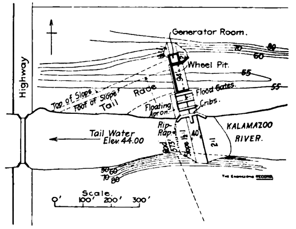
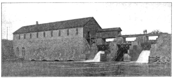
The construction of this power plant was begun in September, 1898, and completed in one year from that date. As shown by the small general plan, the generator house, wheel-pits, and flood gates were located on the flats at one side of the river, and extend transversely to the valley out to the bank of the stream, a distance of 231 feet. No deep-water coffer-dams were necessary, and the flow of the river was not materially disturbed until these structures were nearing completion. Then the river was closed off, and raised ten feet by means of stone-filled cribs and stop-logs, and the water diverted through one of the three twenty-foot flood-gate openings left temporarily at a lower level for this purpose. After this the earth embankment, with two lines of double-plank core wall, was completed without difficulty.
FOUNDATIONS AND CRIBS.
As shown by the sections, the foundations for wheel-pits and flood-gates consist of timber cribs, with stone filling, but the cribs beneath the wheel-pits were filled entirely with gravel concrete. These cribs are of six-, eight-, and ten-inch flat timbers thoroughly drift-bolted together, and there are three longitudinal lines of sheet piling extending through the crib-work; also a row of round piles at the down stream face. The wheel-pit is 94x16 feet, and is inclosed by masonry walls standing on the concrete-filled cribs, below the level of tail water. This masonry is of high-grade rubble, composed of broken bowlders laid in 1:2 natural cement mortar. The main dam, or front wall of wheel-pit, is nine feet thick at the base, five feet at the top, and twenty-nine feet high, and is tied together with iron bars one and one-fourth inches in diameter, with bent ends embedded transversely in the wall at intervals of six feet. There is also a line of sixteen one- and one-half-inch anchor rods extending back into the cribs.
TURBINES.
There are four pairs of forty-five-inch horizontal wheels set in line and coupled to a single ten-inch shaft, which passes through a stuffing box into the generator room, and is coupled to a 1,500-kilowatt, three-phase, alternating generator as a single unit. Each pair of wheels discharge centrally into a common draft tube eight feet in diameter, fitted below with a circular elbow embedded in concrete in the crib-work, and discharging horizontally at the down-stream face of the structure. The wheels are the Samson type, built by James Leffel & Co., of Springfield, Ohio, and develop a total of 2,800 horse-power. The two pairs of wheels nearest the generator are controlled by a Lombard governor, and the farther two pairs by a hand wheel.
EXCAVATION AND PUMPING.
The soil at the location of the dam is largely gravel, and much artesian water was encountered in the deeper excavations, one eight-inch and two six-inch centrifugal pumps being required to keep the pit free from water. Two thresher engines and one stationary engine and boiler were used to run the pumps. Pumps ran at 425 revolutions per minute, and consumed a total of four to four and one-half tons of coal in twenty-four hours. The cost of pumping, including all items of repair, piping, fittings, oil, labor, etc., was $30.00 per day for the three pumps. The gravel filling in the stone-filled cribs was washed in with a three-inch hose as the work progressed, and cost to place forty-eight cents per cubic yard.
CONCRETE.
The concrete used in foundations and crib-filling consists of one part of Louisville cement and five parts of bank gravel taken from the excavation and used without screening, as it was found by repeated trials to contain, within close limits, the proper proportion of sand and fine gravel to fill the voids. This concrete cost in place $2.35 per cubic yard.
STONE MASONRY.
Bowlder stone, from the surrounding country, of which 1,300 cords of 128 cubic feet were used in masonry and crib-filling, cost $4 per cord delivered. Sixteen thousand pounds were reckoned as a cord, and paid for by weight. The cost of the rubble masonry was $3.05 per cubic yard, exclusive of cost of stone.
FLOOD-GATES.
Three 13 x 20 foot Taintor flood-gates are set between crib piers, and are raised by a crab, which ordinarily stands in the crab-house over the flood-gate nearest the wheel-house, but which may be run out on a track over the other two gates. One gate is capable of passing the entire high water flow of the river. The others are for use in case of the emergency of an up-stream dam giving way.
The upper portions of the cribs are sheeted with one course of two-inch plank on the down-stream sides, and two courses of planks on the up-stream sides. On the down-stream side of the flood-gates the water passes over a floating apron consisting of a submerged timber crib structure one hundred feet long, twenty feet wide, and five feet deep, with plank bottom, filled with stone and covered on top with five to seven-inch poles spiked on in the direction of the flow. This apron lies close to the face of the flood-gate cribs, to which it is anchored by short chains.
EMBANKMENT.
The earth fill across the river is composed of clean sand and gravel, all surface soil being carefully excluded. The two lines of plank core wall in this embankment are sixteen feet apart, and extend up to within five feet of headwater level. When the full head of water was raised, there was some seepage through this embankment and through the main masonry wall, mostly about halfway up on the wall, also into the pit beneath the generator, which was lined with five feet of concrete; but this seepage through the masonry and concrete gradually became less and less, and in sixty days stopped entirely, while that through the embankment is greatly reduced.
ELECTRIC PLANT, ALLEGAN DAM.
JAMES B. FOOTE, ELECTRICIAN, KALAMAZOO VALLEY ELECTRIC
COMPANY.
THE generator, which is connected direct to the water-wheel shaft, is 1,500-kilowatt capacity, 60-cycle, three-phase, revolving field, generating current at 2,300 volts. Speed of the machine and wheels is 180 revolutions per minute.
The current is led from the generator through an oil break switch and automatic circuit breakers, ammeters, etc., to the step-up transformers, which are three in number, of 500 kilo-watt each, raising the pressure from 2,300 to 25,000 volts when the transformers are delta connected, or 40,000 with Y connection.
These transformers are oil and water cooled, water for cooling being furnished by a small motor-driven pump, taking water from a drive well. At present the transformers are being run with delta connection at 25,000 volts.
The current is taken from the transformers through lightning arresters to the high-tension switchboard, where the current is led off to the two circuits, one going to Allegan, five miles west, and the other going to Kalamazoo and Battle Creek, respectively twenty-two and forty-six miles east.
The line is No. 4 B. & S. medium-drawn copper wire, on poles of thirty-five to sixty feet in length, set along the country road; the cross arms are ten feet long, and 3 3/4 x 4 3/4 feet cross section, and are fastened to the poles by one 5/8-inch bolt and braced by two iron braces.
The pins are fifteen inches in length and two inches in diameter where they pass into the cross arm, and are made of white oak and boiled in oil.
The insulator used is the Provo insulator made by the Hemingray Glass Company. These insulators are seven inches in diameter and five and one-half inches high, and when mounted on the pin the lower petticoat clears the arms six inches.
Wherever the line crosses the road, or angles in such away that if a pole or insulator should fail, the wire would drop into the road, two poles are used with double arms, the poles set three feet apart. This diminishes the chances of the wire getting into the highway through breakage of insulator or failure of pole, pin, or cross arm.
|
The first substation on the transmission line after it leaves the power house is at Otsego, six and one-half miles from the dam. Here the current is stepped down from 25,000 to 2,500 volts, and used for lighting the village. Alternating series inclosed arc lamps being used on the streets, run from a series transformer, and constant potential alternating arcs run off the incandescent mains, and are used in many of the stores.
The next substation on the line is Kalamazoo, twenty-two miles from the power house. Here the current is run through high-tension switches and lightning arresters to two banks of transformers: one bank of three 250-kilowatt, reducing the pressure from 25,000 to 375 volts, for use in the rotary converters; the other bank of three 250-kilowatt, reducing the pressure from 25,000 to 2,500, for use in lighting.
There are two 300-kilowatt rotary converters installed here, one being used for power purposes, and the other for street railway. The local lighting distribution is accomplished by running single-phase circuits out of each of the three phases of the incoming current.
For the commercial lighting, 100-kilowatt transformers are used to step the current down from 2,500 to 230 volts, and connecting to three-wire distributing mains. From the secondary side of these transformers, pressure wires are run back to the station. An automatic induction regulator operating in each of the feeders, maintains the pressure constant on the secondary distribution.
All the lighting, both arc and incandescent, in the business portion of the city, is done by these large converters. There are at present connected to these distributing centers, something over four hundred constant potential alternating inclosed arc lamps, besides a large number of incandescents and small motors.
From Kalamazoo substation, the line extends twenty-four miles to Battle Creek. Midway between Kalamazoo and Battle Creek, at Augusta, a substation is being built which will contain three 300-kilowatt rotary, and three 225-kilowatt step-down transformers. These transformers have a set of coils wound on the cores with the rotary coils, which will give 2,500 volts for lighting the towns of Augusta and Galesburg.
This rotary station, together with those at Kalamazoo and Battle Creek, will furnish power for the interurban railway line extending from Kalamazoo to Battle Creek, which is now nearly completed.
The Battle Creek substation and lighting distribution is almost an exact duplicate of the one at Kalamazoo, with the exception that there are only three step-down transformers, and that the secondary coils for furnishing current for lighting and to the rotary converters, are wound on the same core.
A telephone line consisting of two No. 10 galvanized iron wires run on brackets seven feet below the transmission line, and transposed every fifth pole, extends the entire length of the transmission line. Contrary to the prediction of many telephone men who said it would not work, this line is giving excellent results.
There is one complete spiral in the transmission line between the dam and Kalamazoo, and also one between Kalamazoo and Battle Creek.
A contract has just been let for conductors for another line from the power house to Kalamazoo, which will be run on the same set of poles as the present line. This will be of aluminum No. 2 wire, made by the Pittsburg Reduction Company.
All the electric machinery and apparatus in all the plants are of the General Electric Company's manufacture, and has given excellent service and satisfaction from the start.
