[Trade Journal]
Publication: Ceramic Industry
Chicago, IL, United States
vol. 4, no. 1, p. 38-41;44-50;52, col. 1-3
The Tunnel Kiln
Most Complete and Up-to-Date
Information on This Subject Available
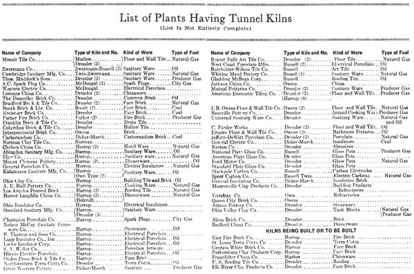
Part IGeneral Data--Operation Advantages, Disadvantages THERE are at present in this country and Canada more than 112 tunnel kilns of all types and designs. These are not all successful and are not all operating. Some of them are now under construction. A practically complete list of kilns, their owners and products manufactured appears elsewhere in this article.
A variety of products is represented in this list, including dinnerware, refractories, glass pots, sanitary ware, stoneware, electrical porcelain, face brick, common brick, hollow tile, drain tile, roofing tile, terra cotta, floor and wall tile, art ware, insulating brick, abrasives, carbon electrodes and china.
| |||
| Didier-March Kiln at General Electric Co., Schenectady, N. Y. Described in Text. |
Advantages of Tunnel Kiln The thing which has prompted the installation of tunnel kilns in practically all cases has been the desire to reduce costs. In this feature the tunnel kiln offers decided advantages over the periodic type. Some of the general advantages are:
1. Constant Firing Conditions In firing periodic kilns, the time temperature curve will depend upon the firemen, the conditions of the kiln, the fuel, the weather and perhaps some other influences. In the tunnel kiln, it is necessary only to hold a certain fixed temperature, while the rate at which the ware is heated is controlled mechanically, and is dependent upon the rate at which the cars are moved thru the kiln.
2. Economy of Fuel The burned gases can be cooled to practically any degree (dependent upon the length of the kiln), before being discharged into the atmosphere. The fired ware and kiln cars moving slowly toward the exit end, give up their heat to incoming secondary air for combustion and can be cooled to practically any temperature (again dependent upon kiln length). The loss due to radiation is less than in any other type of kiln. In a properly designed tunnel kiln, a saving in fuel of from 35 to S5 per cent. over periodic kiln operation can be expected depending, of course, upon the efficiency and design of the latter. In the tabulation of tunnel kiln data (printed elsewhere in this issue) the savings of nine manufacturers averaged 63.28 per cent.
3. Reduced Burning Time Savings of 30 to 75 per cent. in burning time is common. Ware can he burned in from 50 to 72 hours. This includes the cooling time.
**4. Economy of Labor All placing of ware is done at one general location as is also the unloading of the cars. This permits the introduction of new and more efficient methods of sorting, stocking and shipping of ware, altho very few tunnel kiln plants have exercised this advantage. The firing of all fuel is centralized. Cleanliness and order are far easier than with other types of kilns.
The savings in labor on the plants of ten manufacturers, in the tabulation printed elsewhere in this issue, average 28.5 per cent. Labor savings are not always possible, however.
5. Improvement in Quality and Increase in Number of First Quality Products This is usually the case, especially in the burning of the heavy clay products such as brick, tile, and so forth. It is not always true, however, in some instances the tunnel kiln being unable to show an advantage over the product of the periodic kiln.
6. Extra Sagger Service When saggers are used their life is usually increased due to easier handling and less weight of kiln settings.
Offsetting these advantages to a certain extent is the high cost of installation of a tunnel kiln and care equipment as compared with periodic kilns of the same capacity. In the case of pottery a tunnel kiln costing between $75,000 and $100,000 will produce approximately the equivalent of eight to ten periodic kilns of the average size. These kilns could be erected at a cost of from $50,000 to $80,000.
General Disadvantages Among other general disadvantages it has been found that it is difficult to know definitely what length to construct a kiln to give sufficient time for the products to receive the required time-temperature treatment. Spalled and cracked ware due to improper water-smoking; uneven burning due to lack of soaking; dunted or air checked ware due to too rapid cooling are some troubles encountered in improper construction of zone lengths. This, however, is not a basic fault in the principle of the tunnel kiln, but it is a problem made difficult because of lack of actual knowledge of how any particular clay will act in a tunnel kiln. The result of this situation is that, altho by slowing or speeding up the cars the ware can be burned properly, the capacity of the kiln becomes an uncertain quantity.
|
Cars wedging themselves on the rails due to expansion and poorly fitting trucks give trouble sometimes, but it is a difficulty that proper precautions will eliminate.
Another disadvantage is the kiln's comparative inflexibility. In order to obtain the maximum economies, it is necessary to operate the kiln continuously at full capacity. Production can be cut down by placing empty cars and in some kilns by cutting out some of the fire boxes and reducing the rate of speed at which the cars travel. When considering this it must be borne in mind that periodic kilns also become more costly when they are not rotated at their best efficiency. It is entirely probable that some tunnel kilns can be shut down to 50 per cent. of their capacity before becoming as costly to operate as periodic kilns.
Item of Maintenance Whether or not the cost of maintenance favors the tunnel kiln is somewhat problematical. If a tunnel kiln is well constructed with due regard for the temperature to which it will be subjected, there should be comparatively little maintenance to the tunnel. The heat curve in the tunnel is constant and the refractories are not subjected to racking strains of expansion and contraction. The biggest item of maintenance is undoubtedly in the cars. The refractory top of the cars is constantly expanding and contracting as it moves thru the tunnel and this strain shortens its life. Then, too, the handling to which the cars are subjected when they are pushed about the plant and when the ware is set upon them often results in damage which is an item on the maintenance charge.
Replacements in Periodic Kilns In the case of periodic kilns maintenance is higher on the refractory crown. Fire boxes and bag walls are expensive to keep in repair. The reason for this is well expressed by the Clay Products Cyclopedia which says:
"In periodic kiln firing a large mass of ware is heated by furnaces located around the outside of the mass. In order to reduce the firing time as much as possible, the temperature carried in the furnaces is necessarily exceedingly high, which results in severe punishment to the furnace linings. In the case of the tunnel kiln, a relatively small mass of ware gradually approaches the high fire zone. It is possible to have far greater furnace power per unit mass of ware, with the result that it is not necessary to have a furnace temperature so much in excess of the desired ware temperature as is the case with periodic kilns. The advantage is evident. As a specific example of this, in a recently constructed kiln, the greatest furnace temperature was found to be only 30 deg. F. hotter than the highest temperature indicated in the tunnel."
Optical pyrometers have recorded temperatures from 2,500 to 2,800 deg. F. in the fire boxes of periodic kilns burning ware to a temperature of 2,200 deg. F. or less.
A word should here be inserted about the twin tunnel kiln, which some ceramists claim to be the kiln of the future. One of the biggest arguments in its favor is its low cost of construction. A twin tunnel kiln can be built at lower cost than periodic kilns of equal capacity. The twin tunnel practically doubles the capacity without a corresponding increase in construction cost.
Most twin tunnel kilns are designed so that the ware in the two tunnels moves in opposite directions. The one tunnel comprises the water-smoking and preheating zones and the other the firing and cooling zones.
The general principles in the operations of the modern tunnel kilns are to maintain a time-temperature curve in a comparatively narrow tunnel usually between 200 and 350 feet in length, thru which the ware moves on cars. The ware moves thru three distinct zones in the tunnel, the preheating, the high fire and the cooling zones. Fire boxes are located in the center of the kiln and a system of flues and fans usually is used to draw the heat toward the entrance end of the kiln. In this way a gradual rise in temperature is provided. Air for oxidation is drawn from the exit end of the tunnel past the ware, thus gradually cooling the loaded cars to a temperature which makes it possible to handle them and at the same time preheating the air for combustion so that efficient combustion is obtained.
Exactly how these principles are developed requires a description of the different types of kilns now in use, since each type has embodied different features of design and in some instances, as with the muffle type kiln, new principles have been evolved.
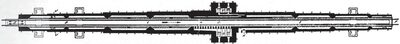
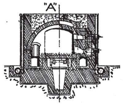
Probably the first kiln to be used successfully in this country was the Didier-March type, developed by the Didier-March Co., at Keasbey, N. J. One of this company's most successful installations, altho often modified, is still in use at the General Electric Co., and is used for burning electrical porcelain. This kiln is described very completely by Lawrence E. Barringer, of the General Electric Co., in Volume XVIII, Trans. of the American Ceramic Society. A diagrammatical plan of the kiln taken from this volume is published on page 39.
| |||
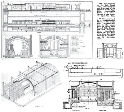
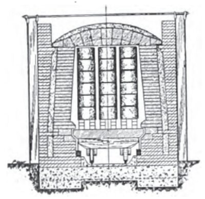
| Typical Cross - Section of Harrop Tunnel Kiln. |
| |||
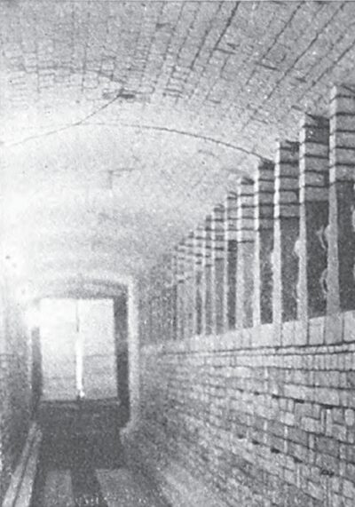
| Interior of A Marlow Tunnel Kiln Showing Arrangement of Flues. |
Description of General Electric Co. Kiln The charging end of the kiln is located at A. B and C are the preheating zones, and D the firing zone. The cooling zone is indicated by E.
"At a point G- between the charging and discharging ends of the kiln the four grates for direct firing are located, two on either side, and from the base of the combustion chamber," says Barringer. "This combustion chamber is separated from the main tunnel by an inner wall, and the products of combustion pass thru the tuyeres H and enter the main tunnel where they become diffused and circulate around the ware, successively passing thru and into the zones, C, D and B. At the point J the waste products of combustion and steam pass out of the kiln into the stack.
"Air for combustion enters the kiln thru ports in the walls at the discharge end. This air passes thru 'serpentine' flues and becomes preheated by contact with the cooling ware. As the ware cools, the heat units are given up to the incoming cold air, and this preheated air passes on until when nearly to the firing zone it is divided, part of the air passing under the grate bars to be used for combustion (primary air) and part of the air being deflected into the kiln chamber to complete combustion of the fuel gases (secondary air). The heated combustion gases pass thru the tunnel upward the charging end and heat up the incoming ware, leaving the kiln thru the stack flue at a point about ten feet from the charging end of the kiln, as indicated by J in the drawing.
Altogether about seven Didier-March kilns were built.
The Dressler Kiln The Dressler kiln of the American Dressler Tunnel Kilns, Inc., has the distinction of having most installations of any one make. The Dressler company has developed several types in both muffle and open fire field and has some highly successful installations.
When Dressler introduced his muffle kiln he brought to the ceramic industry an entirely new principle of continuous firing in that the gases of combustion in his kiln did not come into contact with the ware. Essentially it consists of a tunnel which can be divided longitudinally into two Portionsthe heating zone which occupies rather more than half the length, and the cooling zone. Inside the heating zone there are two lateral tubes placed on either side of the oven and running towards its mouth. These tubes have an almost triangular cross-section and are built up of sets of three hollow pieces.
The gases are burned in these tubes which are known as the "combustion chambers." They are entirely independent of the structure 'of the kiln proper and are supported upon cradles placed at intervals and which are free to move on a flat bench covered with a thin layer of sand.
Dressler Kiln Not a True Muffle The Dressler differs from the true muffle insofar that there is no structural connection between what corresponds with the inner and outer walls of the muffle. A water gage is attached to the combustion chambers near the point of entry of the gases, and the pull of the fan is so adjusted that there is always a depression equal to about one-thirty-second of an inch of water in the chamber. It is said that this is sufficient to prevent the passage of any gas from the chambers to the oven.
Heat from the gases has to pass thru the chamber walls by conduction. The air around the combustion chambers is heated and rises to the top of the oven. Here, it meets the ware, is cooled and drops down channels provided in the wall and the trucks.
Dressler Open Fire For many yeaits the Dressler organization confined its efforts to the muffle kiln, but recently the company has developed an open fire kiln. The first installation was made at the plant of the Kreischer Brick Co., Tottenville, Staten Island, N. Y. This is a coal fired kiln 217 feet 7-1/2 inches January, 1925 long with three fire boxes on each side. The principal feature of this kiln and wherein it differs from other kilns of the open fire type is the means employed for circulating the products of combustion thru the ware. The natural tendency, of the hot gases is to follow the lines of least resistance along the top and sides of the ware, rather than thru the ware itself. Dressler has developed a scheme whereby the draft in the heating chamber is reversed periodically, at any desired intervals, so that it passes thru the kiln first on one side and then on the other. While this transition is going on the products of combustion pass thru the ware on the cars to reach the other side of the kiln.
In this kiln the refractory tops of the cars have a pitch of one-half inch towards the center of the cars to counteract the tendency of the ware to pull outward during burning.
The Harrop Kiln The Harrop car tunnel kiln is direct-fired, possessing heat transfer characteristics analogous to the usual periodic kiln.
The maturing zone occupies approximately the center portion of the kiln and is provided with furnaces on both sides in staggered relation, opening directly into the tunnel and delivering heated gases into direct contact with the car setting. The length of the maturing zone is designed to suit the particular ware to be fired, its maturing temperature and the desired kiln capacity.
For heavy wares, water-smoking means are provided. This operation is accomplished at the charging end of the kiln by pure warm air drawn from the cooling end.
For all wares made from crude clays, oxidizing means are provided thru the introduction of pure pre-heated air in the maturing zone, thus insuring sufficient pure air for oxidation, without passing same thru the furnace zone and lowering combustion efficiency.
The principal cooling means consists of introducing air to the tunnel proper at the discharging end. Additional cooling is provided by hollow side walls and crown flue.
To overcome the natural tendency in all kilns for the top to become hotter than the bottoms, battered lining walls are used, which give greater space for horizontal gas travel at the bottom than at the top. This construction has proven to be practically a necessity in giving the much desired uniformity of ware temperature.
Sand seals are employed to separate the tunnel proper from the truck compartment and means are provided to maintain the same pressure below the cars as in the tunnel above at all points in the length of the kiln, so that a minimum of leakage will take place from the truck compartment up into the tunnel or vice versa.
The Russell Kiln The Russell single tunnel kiln is designed and built by the Russell Engineering Co., St. Louis, Mo. It is the direct fired type, i. e. one in which the gases of combustion enter the kiln proper and completely encircle the ware on the kiln car.
The kiln itself is a long tunnel with straight side walls and a low arch. The walls and arches are fire brick and common brick insulated in the proper zones. The interior of the kiln is smooth thruout the entire length and built so that the heat is confined to that portion occupied by the ware. The sand seal is used to keep the heat from the bottom of the cars.
| |||
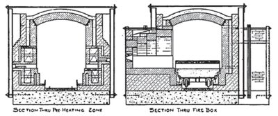
| Cross - Section Thru Holcroft-Lengersdorff Kiln in Two Firing Sections. |
Fire boxes are located midway between the ends of the kiln and large enough to permit complete combustion to take place in same. It can be designed for gas, oil or coal. They are spread out so as to give a long hot zone.
The hot gases from the fire boxes travel down the kiln proper, being drawn towards the entrance end by an exhaust fan.
Control of preheating zone conditions is provided by dampers and side wall flues between the fire boxes and exhaust fan.
| |||
| Two Cross - Sections Thru the Russell Single Tunnel Kiln. |
Other features of this kiln are the method of cooling thru hollow side walls and hollow arch in the discharge end, the method of preheating air for combustion and the construction of the kiln cars with insulated refractory decks.
The smallest Russell kiln is 32 inches wide by 227 feet long and the largest 6 feet wide by 360 feet long. Several kilns of intermediate sizes are in operation.
A number of building products manufacturers have attempted to develop kilns of their own design, in some instances with fair success. Among the privately developed kilns is a particularly successful installation at New Toronto, Ont., designed and built by Geo. W. Booth, of the Booth Brick & Lumber Co.
This is an open fire kiln burning red face brick. Coal is used to fire it and the kiln has six fire boxes on each side. Mr. Booth has built two kilns; the first one was 250 feet long and was successfully operated for two years. A second one was then built 335 feet long. In this kiln a bag wall protects the ware from the flames to a certain extent. Products of combustion enter the kiln thru small holes cut in the bag wall opposite the fire boxes at a level slightly ever the car tops. One fire box is left open entirely for the purpose of flashing the brick.
The clay at this plant has a low shrinkage and thus the shrinking of the bottom brick, when exposed to the fire, is not sufficient to disturb the setting. The top of the setting is pulled outward sometimes, showing that some shrinkage has taken place where the flame tip touched the ware.
The time-temperature curve is developed by drawing off the products of combustion thru a series of openings extending into the preheating zone and opening into a flue which runs along the side of the tunnel. No means for recirculating the heat thru the kiln is provided, but the hot gases are drawn off and utilized for drying. This kiln also has a hollow crown forming a flue in which air is heated by radiation and drawn off to the dryer.
The Holcroft-Lengersdorff Kiln One of the latest types of tunnel kilns to invade the American market is the Lengersdorff, developed in Germany and brought to this country by Frank H. Riddle of the Champion Porcelain Co. Refinements and changes are being made on it by the Holcroft Co. This kiln, it is said, is used in Germany for burning high tension insulators, mosaic tile, fire brick, common brick, hollow tile, biscuit and glost whiteware, stoneware and vitreous china.
This kiln differs in many particulars from others, but the chief difference is in the principle of heat application and heat recovery. A variable arrangement has been devised for the location of the burners in the high temperature zone, for the carrying off of the exhaust gases in the preheating zone, and for the recovery of heat directly or indirectly from the cooling zone.
The charging end of the tunnel has been converted into what amounts to practically a separate compartment for drying and water-smoking. Heat from the cooling zone is introduced into the water-smoking section. The introduction of this heated air is regulated and after becoming charged with the volatile products of drying process it is removed. Its removal also is regulated.
In the Holcroft-Lengersdorff kiln the various zones, drying, preheating, firing and cooling are not necessarily of fixed length as is the case in the average tunnel kiln. Lengersdorff claims for this kiln that --
1. The high temperature zone can be shifted considerably in a horizontal as well as in a vertical direction.
2. The burners work against one another and can be regulated so that the flame tips of opposite burners meet in the tunnel.
3. In the high temperature zone each individual pressure burner is enabled to draw by suction hot combustion air directly from the cooling zone of the kiln, so that combustion takes place in the combustion chamber instead of in the tunnel.
4. In the preheating zone each individual pressure burner is enabled to draw by suction hot combustion air indirectly from the cooling zone of the kiln, so that combustion takes place in the combustion chamber instead of in the tunnel.
5. The preheating zone also can be shifted at great length in a horizontal as well as vertical direction.
6. In the preheating zone several exhaust ports arranged opposite each other remove the products of combustion and moisture.
7. A separate drying zone is built in the kiln in order to introduce at various points in this zone hot air which can be regulated, and to draw off this hot air after it has become laden with moisture from the drying ware. The drawing off of the gases can also be regulated.
8. The tunnel cross-section is enlarged in the cooling zone (between the cooling and high heat zones) in order to lead highly heated air out of the cooling zone to the separate burners.
9. Several sections of recuperators are arranged in the cooling zone in order to insure a suitable individual cooling for the burned ware.
An exhaust fan works between the tunnel and the stack in order to lead the products of combustion and the volatile products of the drying process out of the drying zone with a constant draft which does not de-pend upon atmospheric conditions in the stack.
Another kiln which has been brought from England to this country recently is the Marlow kiln. This kiln, an open fired recuperative type, designed by J. H. Marlow, was the first built 332 feet long (in America) for the Mosaic Tile Co.
The air used for combustion is first preheated by being drawn thru flues along the tunnel and is then superheated when it passes thru the firing zone.
Later, this air meets the incoming combustion gases, which have also been preheated. The volume of air consumed is regulated by the expansion of gas and size of the orifice thru which it enters into the combustion chamber. This in turn is controlled by the temperature of the hot zone. Thus a semi-automatic operating condition is obtained.
It is claimed for this kiln that it is possible to vary the temperature up to 70 deg. F. between bottom and top of car in either direction, i. e., the bottom can be controlled at a temperature up to 70 deg. F. hotter than the top, or vice versa.
Cars are not sand sealed but are built with staggered side construction. Running water thru iron pipes under the cars helps to cool them. They are pulled instead of pushed.
Miscellaneous Types There are, of course, many other types of kilns besides those described, but information is not available on all the tunnel kilns developed privately. Some of the kilns designed by manufacturers for their own use are more or less successful. Among the more generally known are the Farber kiln at the Farber (Mo.) Fire Brick Co., the small cross-section kiln for firing spark plug cores at the A. C. Spark Plug Co., the kiln recently put in operation by the Vitrefrax Co. at Los Angeles for burning refractories, and the kiln now being built at the Western Electric Co. of the same design as the A. C. Spark Plug Co. kiln.
| |||
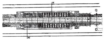
| Plan View of Firing and Part of Cooling and Preheating Zones of Holcroft Lengersdorff Kiln. |
By far the greatest number of tunnel kilns are in use by manufacturers of the higher grade of clay products. Their use in the field of heavy clay products, especially building products, has been less rapid than in the porcelain and whiteware industry. The reason for this has been that, the value of building products being comparatively low, the high initial cost of the kiln has reduced the possibilities of making savings. For example, the cost of a tunnel kiln 300 feet long will be, let us say, $100,000, regardless whether it will be used for firing face brick or sanitary ware. But the 24 hour production of the tunnel kiln in face brick will be worth probably $450, while in sanitary ware the production of such a kiln would be worth probably $2,600. Figuring an interest on investment of seven per cent., approximately $20 per day will have to be charged against $450 in one case and $2,600 in another. The fuel and labor savings will probably be equal or slightly in favor of the face brick kiln. It can readily be seen, therefore, that the manufacturer of the low grade clay product does not obtain the same dollars and cents benefit, from a tunnel kiln as the producer of high grade ceramic ware.
This should not serve to discourage manufacturers of heavy clay products, however, for a successful tunnel kiln installation can produce savings in fuel and labor which are startling.
The reason for this is the appalling waste in fuel which is occasioned in even the best periodic kilns. The great mass of brick work which must be heated every time a charge of ware is fired requires an enormous amount of fuel. Exactly what this figure is not known, but very evidently it is considerable.
Where Heat in Periodic Kilns Goes
The following heat distribution tables compiled by A. V. Bleininger and published in the Trans. of the American Ceramic Society, Volume X, show what an immense amount of heat is absolutely wasted:
Sewer Pipe Kiln
Heat lost by the waste gases--18.60%
Heat taken up by the ware--5.70%
Heat lost by ashes--4.58%
Heat taken up by the kiln and lost by radiation--71.10%
Paving Brick Kiln
Heat lost by waste gases--29.90%
Heat taken up by the brick--11.30%
Heat lost by carbon in the ash--3.90%
Heat taken up by the kiln and lost by radiation--54.90%
Terra Cotta Kiln
Heat lost by waste gases--26.80%
Theoretical heat necessary to heat up charge--12.57%
Lost by carbon in the ashes--1.90%
Heat taken up by kiln and lost by radiation--59.73%
Common Brick
Heat lost by the flue gases--27.33%
Theoretical heat required to burn brick--19.55%
Heat lost by unburned carbon--3.51%
Heat taken up by kiln and lost by radiation--49.61%
In these four calculations the heat taken up by the kiln and lost thru radiation is in every case the greatest amount. This amount has, in some instances, been reduced thru the use of insulating materials. It is in this figure that the tunnel kiln can produce its greatest saving because it can be almost perfectly insulated. The fuel savings made in tunnel kilns now operating over periodic kilns can be seen in the tabulation printed elsewhere in this article.
| |||
| Photograph of Firing Zone of Holcroft-Lengerdorff Kiln Showing Location of Burner Holes. |
An interesting comparison with the preceding heat distribution tables can be made with the following one of a tunnel kiln burning porcelain in Germany. These figures as well as the chart published on this page, from which they were taken, bring out some interesting facts. The heat balance shows conclusively that it is just as important to insulate the preheating and cooling zones of a tunnel kiln as the firing zone. According to the chart, heat losses in the cooling zone are almost as great as in the preheating and high fire zones combined. The difference being only six per cent.
Heat lost by waste gases--18.26%
Heat taken up by the ware--15.33%
Heat lost in radiation preheating and hot zones--36.60%
Heat lost in radiation cooling zone--30.58%
The chief reason for the failures of tunnel kilns where they have occurred, has been the fact that experience in tunnel kiln building and operating has until recently been so limited that practically every kiln built has been an experiment. Very few installations, indeed, have been successful from the start without first adjusting some feature of the kiln, whether it be the length, the speed of moving the cars, the setting of the ware, changing of the time-temperature curve, car equipment (especially refractory tops) character of the fuel, or what not.
Problems of Design These changes are sometimes expensive and sometimes inconsequential. The cost of making them must be added to the initial cost of installing the kiln. They are legitimate costs and should be considered so by the manufacturer who is installing a kiln. It is difficult to foretell exactly how any clay will act in a tunnel kiln and what its requirements are. Every clay products manufacturer knows why this is. Few pottery bodies act alike when they are being fired and the exact conditions must, to a certain extent, be determined by experiment.
This does not apply in the same degree to fine ceramic wares, such as china ware, sanitary ware and other porcelain bodies. The reason for this is that the necessary conditions especially the time temperature curve, can be gaged more accurately and a kiln built to suit these conditions, with reasonable assurance that it will operate as intended. It becomes then a question largely of desired capacity.
Securing Heat Distribution Another difficulty which manifests itself is the securing of proper heat distribution thruout the ware. This, in fact, has always been the greatest problem in kiln operations. Exact data on the difference in temperature in the center of the cars and the outsides and top is not available. That this amounts to as much as one or two cones in many instances can not be denied.
The main draft in any tunnel kiln is toward the entrance end. The course of least resistance for the hot gases is along the top of the cars under the crown and along the sides of the kiln between the cars and the kiln walls. In order to drive heat into the ware itself it is necessary to provide some means of creating a down-draft or cross-draft.
Harrop in his kiln secures circulation by kiln walls inclined toward the top, by niches or recesses built in the walls at intervals, and curtains or drop arches in the crown. The larger space between the kiln wall and the ware at the bottom of the tunnel has a tendency to make the gases travel along the bottom to the exit. At every drop arch the hot gases are also deflected downward into the ware. The recessed areas, which are placed alternately on the sides, by creating a slight negative pressure, also, aid in making the hot gases follow a circuitous route thru the ware.
Producing a Cross-Draft Dressler creates what is virtually a cross-draft by means of a draft reversing mechanism which, at any desired interval switches the draft from one side of the kiln to the other.
In certain Russell kilns a scheme for burning the gases directly under the ware has been devised. Ware is set in such a manner as to form an arch set transversely on the kiln car. Furnaces are set staggered with the exception of the last two. As the cars move forward the arches in the ware gradually come in line with the fire boxes and thus at certain intervals, as the arch in the ware comes opposite the burners on each side, the gases are burned directly under the ware in a manner similar to the well known stove kiln.
Heat Distribution in Muffle Kiln In the Dressler muffle kiln a down-draft is created in the following manner: The muffle is built with walls of hollow sections which are open to the kiln at the top and bottom, providing an opportunity for gases to circulate thru the hollow spaces. The cooler gases naturally drop to the bottom of the kiln and pressure from the hot gases on top forces them into the hollow spaces at the bottom of the muffle. Here they are again heated and pass out thru the top part of the muffle to the top of the ware. Thus a constant circulation of the gases from top to bottom is maintained.
The problem of shrinkage in an open fire kiln is more important to the manufacturer of heavy clay products which are burned without saggers, than it is to the manufacturer of finer ceramics which are protected by saggers. The saggers, having been burned naturally do not shrink.
Part 1IDiscussion of Data in Questionnaire
DESIGNERS and builders of tunnel kilns have had probably a harder row to hoe than the designers and builders of any other single piece of equipment used in the clay industry. More than most other pieces of equipment it has been necessary to develop the tunnel kiln by experiment and a system of cut and try. There are very few kilns, indeed, which were absolutely successful when operated according to the plans prepared on the desks of the engineers. It has been almost impossible to do this because the ceramic industry has lacked the knowledge which comes from observation of actual operation under many different conditions and many different circumstances. Tunnel kilns are successful and there is hardly any danger that tunnel kilns built today cannot be made to operate successfully and economically.
Prepare to Experiment The manufacturer who installs a tunnel kiln should be prepared to do some experimenting with it until it has been adapted to his particular needs. We heartily agree with the manufacturer who says, "Each kiln has its own difficulties and they must be worked out."
Another important consideration is that unquestionably failures of tunnel kilns are often due to inefficient and improper handling as to faulty design. The same coal passer that shovels coal into the fire boxes of your periodic kiln should not be expected to operate so highly technical a piece of equipment as a tunnel kiln.
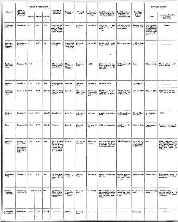
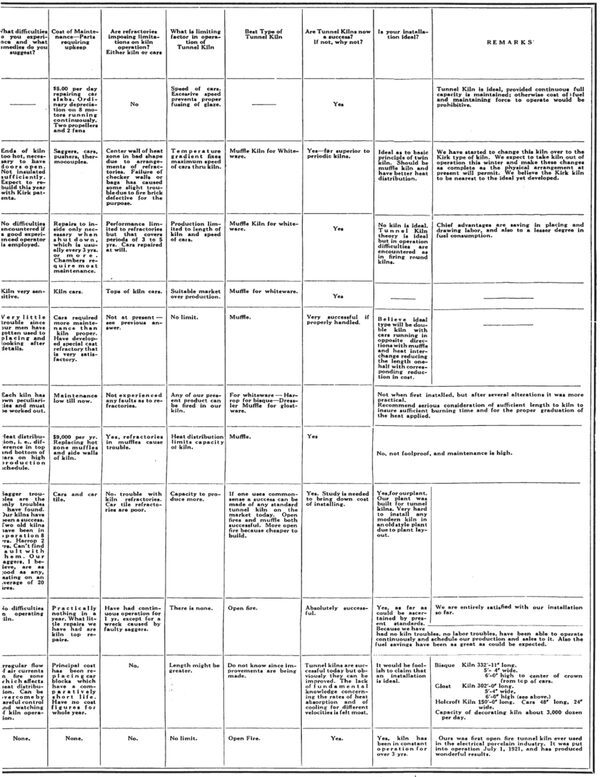
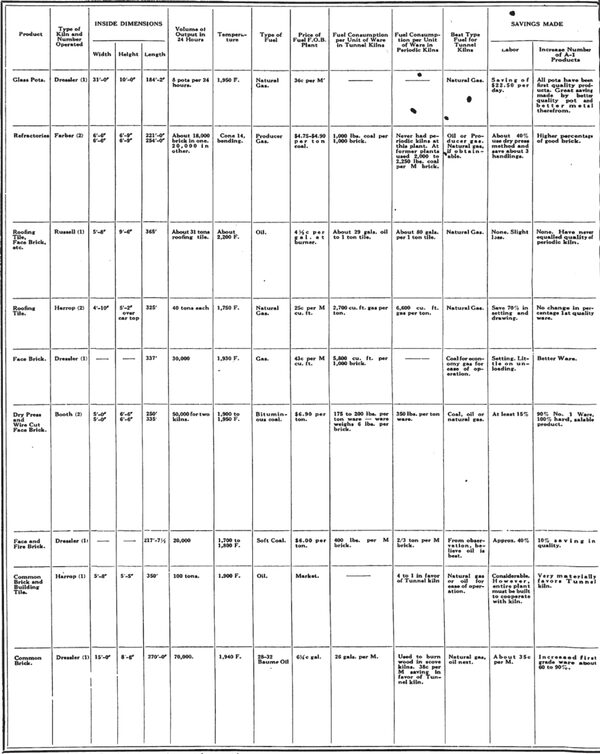
These remarks as Well as those following should be kept in mind when studying the tabulation presented with this story.
Tunnel Kiln Growing More Efficient Tremendous advances have been made in tunnel kiln design. Many of the kilns covered in the tabulation are old types and defects registered in those have, to a large extent, been corrected today. The tunnel kiln today is much like the radio. New ideas and new developments are being made so fast in this new industry that periodically the radio receiving sets become antiquated and out of date. That, however, does not prevent anyone from installing a set and enjoying its benefits in the meantime. Neither should anyone hesitate to install a tunnel if his only reason is to wait for a more efficient design.
In studying the questionnaire tabulated on pages 46 to 49 readers must bear in mind that some of the kilns are older than others, which would affect such items as maintenance and refractories replacements considerably. The tabulation was not made for purposes of comparison of the different types of kilns. Names are given only for the sake of description and clearness.
If you are thinking of installing a tunnel kiln, the questions in which you are most vitally concerned are, "What will it cost me," and "What savings will I be able to make?"
The first question is almost impossible to answer in a general way since it varies widely with every installation. The average kiln would probably cost between $65,000 and $90,000.
Savings Possible With regard to the second question, some figures can be obtained from the reports here presented, which cover installations at 19 different plants. The basis of these articles, however. cover knowledge of experiences far in excess of the number on which data is presented. In fact, the editors have themselves seen over 50 of these kilns in operation on various products and in all parts of the country. The articles are tempered by what was seen on these plants. The following table shows the percentage fuel savings which have been made on nine plants over former kiln equipment (the total which can be calculated):
| |||
| Fuel Saving |
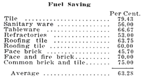
The nine plants have been enabled to make an average fuel saving of 63.28 per cent. by installing tunnel kilns.
Savings in burning time are not given in the questionnaire but this item is almost invariably considerable. 50 per cent. and more has been cut off in many cases. A 35 to 50 per cent. cut in time is quite general.
The savings in labor, as calculated from the results of the questionnaire, are not so great as in fuel, but are nevertheless considerable. It is interesting to note that in some instances manufacturers have reported increased labor costs. The following table shows the labor savings made on ten plants represented in the tabulation:
| |||
| Labor Saving |
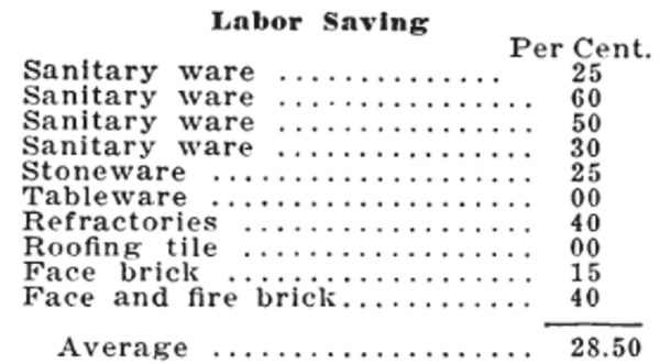
The ten plants, varying all the way from nothing to 60 per cent., have been enabled to make an average labor saving of 28.5 per cent. In this connection, it must be remembered that in most instances the kiln was built under the best conditions that the plant would permit, 'but yet far from ideal. As stated before, the plant should be built around the kiln. Many manufacturers have not as yet changed their setting and unloading methods to permit the greatest economy. Undoubtedly the above figure for labor saving could be increased.
Increased Quality Savings that have been made due to an increase in quality are still lower than labor. A number of manu-facturers replying stated that there was no difference, several indicated a considerable percentage in favor of the tunnel kiln, but did not reduce this to figures, and in one case a lowering of the quality of the ware was reported. The following table shows the savings in increased quality made on six plants represented in the tabulation:
| |||
| Increased Quality |
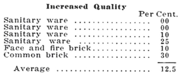
The six plants have been enabled to make an average saving in increased quality of 12.5 per cent.
Some Economies Tile following installations, which are not listed in the tabulation, contain some interesting information:
A plant burning sanitary ware biscuits in a Didier-March kiln 297 feet long, has effected a saving of five tons of coal daily. Producer gas is used and eight tons of Eastern Kentucky coal are required daily. A temperature of 2,170 deg. F. is reached. The kiln has a capacity of 350 pieces and a total of nine men are required to operate it.
A plant burning floor and wall tile in two Dressler kilns has been able to effect a fuel saving of 20 per cent. and a saving in burning time of 66 per cent. The quality of the glost burn was also increased. Natural gas is used and temperatures to cones 4 and 01 are reached in the biscuit and glost kilns, respectively, 400 to 500 square feet of ware is set in saggers per car. The tunnel kilns are equivalent to ten round kilns of 16 foot diameter.
Saves $2,000 Per Month A plant burning art and cooking ware in a Dressler kiln has been able to make a saving of $2,000 per month. Producer gas is used to fire the biscuit to cone 4. Eight round kilns have been supplanted.
One point in tunnel kiln operation which frequently comes under discussion is that of maintenance. Contrary to general opinion, repairs to kiln cars and to the kiln in general are not excessive and, in most of the installations reported, do not amount to a very considerable item. The refractory top of the kiln cars is the particular part which gives most trouble, because it is practically the only part of the kiln which is subjected to the strains and stresses of contraction and expansion.
Probably the most interesting thing brought out in the entire questionnaire is the large percentage of manufacturers who frankly state that, to secure greatest efficiency from it, a plant should be built around the tunnel kiln as a nucleus, instead of endeavoring to fit the kiln to the plant. This does not mean, of course, that it is not economical to build a tunnel kiln on a plant using down-draft kilns. The following is a questionnaire which was received too late to be included in the tabulation.
1. Type of Product.Vitreous china sanitary ware.
2. Type of Kiln.Russell. One twin kiln, five single kilns.
3. Output in 24 Hours.Approximately 1,000 finished pieces. Kiln car loads vary from 8 to 36 tanks per car.
4. Dimensions.Kilns vary from 227 to 282 feet in length.
5. Fuel.Fuel oil.
6. Fuel Consumption. Approximately 18 gallons per ton of material fired.
7. Best Type of Fuel.-1, Natural gas. 2, Oil. 3, Producer gas.
8. Maintenance.Machine parts require the ordinary amount of repairs. Deck tiles on cars require occasional replacement.
9. Are Refractories Imposing Limitations?Refractories in kiln structure are sufficient for the service required of them. This company is making its own deck tiles for kiln cars.
10. Limiting Factor in Operation.Greater length of kilns would permit greater production but kilns are giving the production they were designed for.
| |||
| List of Plants Having Tunnel Kilns (List is Not Entirely Complete) |
|
|
|
|