[Trade Journal]
Publication: Western Electrician
Chicago, IL, United States
vol. 2, no. 24, p. 296-297, col. 2-3,1-3
Dynamo Tenders' Hand-Book.†
By F. B. BADT.
PART V.
CIRCUITS OR LEADS.
CHAPTER XLI.
Outdoor Leads for Arc Lighting.
The wire used for outdoor circuits is mostly what is called underwriters' standard. It consists of a copper wire which is braided with cotton and painted with asbestos to make it uninflammable. This wire is fastened to glass insulators on poles or houses in a way similar to that in which telegraph wires are usually run. Insulated wire, and not bare wire, should be used for tie wire, as the common non-insulated tie wire will cut the insulation of the line wire and possibly cause leaks. The size of arc light conductors varies between numbers 6 and 4, Brown & Sharpe gauge, number 6 being the smallest wire which can be used, according to the rules of the National Board of Fire Underwriters. If the return wire is fastened on the same poles, the positive and negative wires should be kept sufficiently far apart so they can not touch each other when swung by wind. It must be understood that the insulation called underwriters' standard is only an insulation when perfectly dry, and when wet is hardly any insulation at all. If, therefore, the positive and negative wires exposed to rain or moisture of any kind should come in contact with each other or with the ground, a short circuit would be caused. This may cut a number of lamps suddenly out and cause damage to the dynamo. Such an accident, for instance, may burn out the armature or throw off the belt. In very cold weather such occurrences are rare, as frost may make out of a circuit of the poorest insulation one of very high insulation, while on the other hand a thaw or rain may cause all kinds of disturbances. If these disturbances occur during a thunder storm accompanied by rain, lightning is often unjustly accused of having done the mischief, while in fact the poor insulation of the wires is the prinie cause.
Accidents from poor insulation of lines are more frequent than damages caused by lightning, though the latter will always be a ready excuse for anything that may have happened. Recently weather and water-proof insulation have come in vogue, and they are much safer than underwriters'standard wire.
In conducting wires into houses, great care must be taken to prevent rain following the wires. The wire should be fastened to the insulator below the point where it is intended to be led through the wall or a window frame, so the rain would have to run up hill in order to follow the wire, Fig. 35.
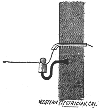 |
| Fig. 35. — Proper Position of Insulator. |
Fig. 36 shows a wood pin and glass insulator, such as are used on cross arms. The latter are fastened to poles by means of lag screws. Fig. 37 illustrates a wood bracket, which can be spiked to poles or houses and provided with a glass insulator. The glass insulators must always be fastened in a nearly vertical position, the closed end on top, so the space between the pin and glass insulator, Fig. 36, will remain dry in rainy weather and secure perfect insulation.
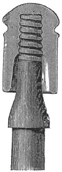 |
| Fig. 36. — Wood Pin and Glass Insulator. |
 |
| Fig. 37. — Wood Bracket. |
Fig. 38 shows a rubber hook insulator. This should for the same reason be fastened with the hook downward. A hole can be bored with a 5/8 inch bit underneath a crossarm and the rubber hook screwed in with a wrench.
An extra heavy insulating material, such as rubber hose or hard rubber or porcelain tube, Fig. 39, must be put over the wires where they pass through walls or partitions.
Poles for lines should be set deep enough in the ground; the depth, of course, will depend upon the soil and the height of the pole. In sand, at least one-fifth of the length of the pole should be buried in the ground, while in rock one-tenth of the length is sufficient. In putting up wires, the season, or, in other words, the temperature, should be taken into consideration, allowing for contraction in cold weather. If, for instance, a wire should be put up very tight in July, it would cause a good deal of' damage in breaking off glass insulators and pins as soon as the temperature fell to zero and caused the wire to contract. Corner poles must be braced or anchored to keep them in a nearly vertical position. See Figs. 40 and 41.
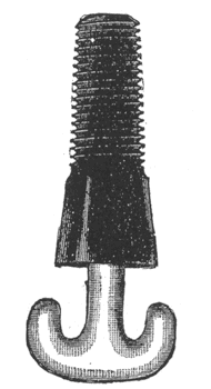 |
| Fig. 38. — Rubber Hook Insulator. |
When a splice is necessary, it should be made after the fashion of the American telegraph splice, Fig. 42, and should be perfectly clean and solidly soldered and then
 |
| Fig. 39. — Hard Rubber Tube. |
well taped with insulating tape. In order to prevent the tape from peeling off, it is advisable to fasten the last turns of the tape to the wire with a few turns of bare copper
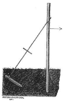 |
| Fig. 40. — Corner Pole Anchored. |
wire, say about number 20. If this precaution is omitted the tape is sure to peel off in time. Most of our electric light lines will show places where the tape is hanging down a couple of feet. Besides, having no insulation on
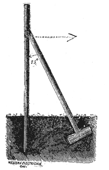 |
| Fig. 41. — Corner Pole Braced. |
the splice, this, of course, does not contribute to the beauty of overhead wires.
Brass line connectors. Fig. 43. are only allowed for inside work where there is no strain on the wires, The set screws should be well tightened, and the connector be run full of solder and taped. Good soldering and taping
 |
| Fig. 42. — American Telegraph Splice. |
of joints will save at least 50 per cent. of all the troubles that occur in an electric light plant. Joints should never be left unsoldered, even if persons who claim to know all about it should think it unnecessary. The best apparatus for soldering joints on line wire out of doors is the gasoline blow-pipe, Fig. 44. Every trace of acid should be wiped off the wire with a moist or oily cloth before taping, to avoid corrosion.
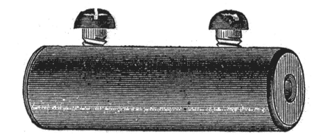 |
| Fig. 43. — Brass Line Connector. |
CHAPTER XLII.
Outdoor Leads for Incandescent Lighting.
The rules which were given for outdoor arc light lines can be applied for incandescent light lines. As the wire used will very often be considerably larger than number 4 wire, the poles, cross-arms and other supports must necessarily be heavier to stand the greater strain, and poles should be set closer together. In a low tension incandescent system, very often bare wires are used, and still more care must be taken to prevent accidental contact of the positive and negative wires with each other or with the earth.
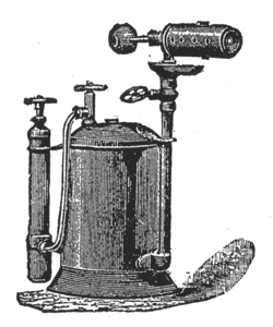 |
| Fig. 44. — Gasoline Blow-Pipe. |
CHAPTER XLII.
Arc Circuits Inside of Houses.
The wires for these circuits should be fastened to porcelain insulators, Fig. 45, and be exposed to view. Owing to the high tension which prevails in arc light circuits, the concealing of these wires is not permitted by the underwriters. The directions given for splicing and insulating hold good also for inside wiring.
In rooms which are exposed to steam or moisture, as, for instance, in'packing houses, wire with a better insulation than underwriters' standard must be used. The moisture which covers insulators and wire would cause considerable leakage, and, besides would corrode the wire. The use of wood cleats or iron staples instead of porcelain
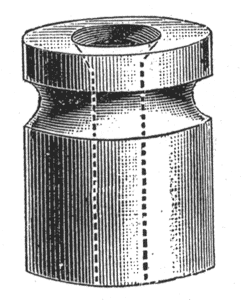 |
| Fig. 45. — Porcelain Insulator. |
insulators should not be permitted in any case, as they are liable to cause grounds and, in fact, have been the source of mischief in a good many cases in years gone by.
CHAPTER XLIV.
Incandescent Circuits Inside of Houses.
In the low tension systems, wooden cleats or wooden molding are permitted for fastening the wires to the walls and ceilings if there is absolute safety from moisture. Underwriters' wire may be used also under the same conditions. If there is any possibility of moisture getting to the wires, the latter should be first-class waterproof insulation. If any ''fishing " has to be done, where wires are to be concealed under floors, above ceilings, or between walls or laths, only waterproof wire can be used. Incandescent wireing [sic] wiring inside of houses requires a good deal of skill and experience, and should only be intrusted to reliable and responsible concerns. Unfortunately, any man who ever fastened a piece of wire for a bell-pull, thinks himself an expert also for incandescent wiring; a good many even important jobs have been done by such men, with the result that, after a great expenditure of money by the owner of the house, the whole system had to be condemned, as not an inch of the wire had been put in properly and cculd be used.
The joints or connections in waterproof wire should be made waterproof also. This is done in the following way: After having spliced, soldered and cleaned the wires properly, cover the joint with hot Chatterton's compound by
 |
| Fig. 46. — Wood Cleat. |
molding it between the fingers to almost the total thickness of the insulated wire. Then cover it with kerite tape and give it a second thin coating with hot compound, or hot asphaltum, and then give it a second coat of kerite tape. Hot liquid asphaltum should be used in lieu of compound where there is danger from sewer or illuminating gas that is prevalent in the soil and basements of houses in large cities.
 |
| Fig. 47. — Protection of Wires Crossing Each Other. |
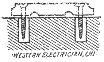
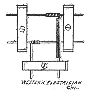
Figs. 46, 47, 48, 49 and 50 show the use of cleats. Fig. 46 shows a familiar form of cleat. Where the positive wire crosses the negative, an extra protection of rubber tube is required to prevent any danger from short circuits, Fig. 47.
 |
| Fig. 48. — Wires in Separate Holes. |
 |
| Fig. 49. — Wires in Same Holes. |
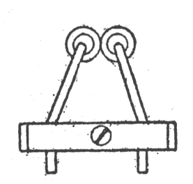
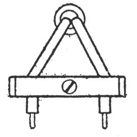
In passing through a wall, each wire should be inserted in a separate hole, lined with a hard rubber tube, Fig. 48 or each wire should be covered with soft rubber tubing and both may be drawn through one hole, Fig. 49, lined with a pipe of non-conducting waterproof material.
 |
| Fig. 50. — Wood Molding. |
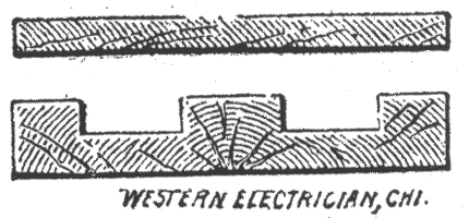
Fig. 50 is a cross-section of wood molding. The lower part is fastened to the wall or ceiling, the wires put in — positives in one groove and negatives in the other — and the cover screwed on. Care must be taken that nails or screws do not touch-the wires.
The safety plugs are put in the circuit according to the rules of the fire underwriters. They must be of such size that they will fuse before the wire they have to protect can get dangerously warm.
CHAPTER XLVI.
Testing.
The circuit should be tested every day for grounds by means of the detector galvanometer or a magneto bell. If a ground is indicated it should be speedily located by disconnecting the circuit in different places and taking each section separately, until the ground is located. [See also. Chapter XXXIX.]
 |
| Fig. 51. — Accumulators. |
ACCUMULATORS.
CHAPTER XLVII.
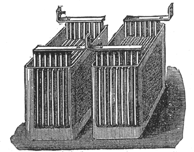
Accumulators, Fig. 51, or secondary batteries, are used for the storage of electricity. They consist generally of glass vessels containing a solution of sulphuric acid and water in which lead plates, insulated from each other, are placed. The positive and negative lead plates are called the electrodes. These batteries are usually charged with shunt dynamos. A chemical change in the plates is produced. In discharging, the plates try to return to their first chemical condition and in doing so they generate a current.
The e. m. f. of an accumulator is about 2 volts. In order to burn 100 volt lamps, 50 accumulators must be connected in series. The maximum current strength they should be allowed to yield is generally given by the manufacturer. It is in the neighborhood of 35 amperes, which can be yielded for ten hours, or, as it is expressed the accumulators can yield 35 x 10 = 350 ampere hours. Hence a battery of 50 accumulators could yield 350 ampere hours at 100 volts pressure. If we had 100 volt 16 candle power lamps requiring 1/2 ampere each, we could, for instance, burn 70 of these lamps 10 hours, or 35 lamps 20 hours, etc.
(Concluded.)
† DYNAMO TENDERS' HAND-BOOK, by F. B. Badt; 100 pages, 70 illustrations; flexible cloth binding; type page 6 x 3 inches; published by WESTERN ELECTRICIAN CO., price $1.
