[Trade Journal]
Publication: Western Electrician
Chicago, IL, United States
vol. 8, no. 14, p. 193, col. 1-2
Experiments with High Tension Currents
at the Oerlikon Works, Switzerland.
C. L. Brown, manager of the Oerlikon Works, Switzerland, recently read a paper for the Electrotechnische Gesellschaft at Frankfort on the transmission of high tension currents. As this paper was based on extensive experiments made in the Oerlikon factory, and proved of considerable interest on the other side of the water, an account of the tests is given herewith for the benefit of American electricians.
 |
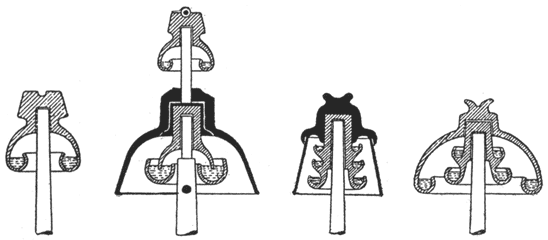
| Figs. 2, 3, 4 and 5. Experiments With High Tension Currents. |
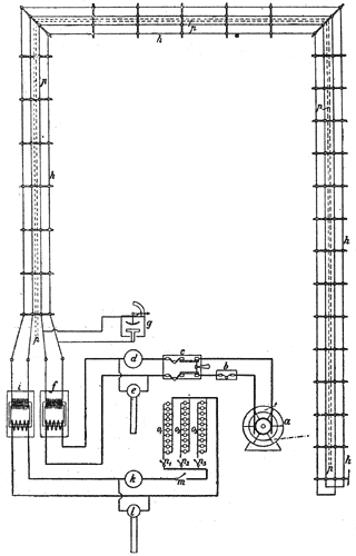
Fig. 1 is a diagram representing the experimental plant; a is an alternating current dynamo with a difference of potential of 130 volts, b is a fuse block for the protection of the dynamo, c is a double pole switch with fuse attachments, d and e represent respectively an ammeter and a voltmeter, f is a main converter, receiving in its primary coil the entire current from the dynamo. The winding of the secondary coil of this converter is 300 times that of the primary, producing, with due allowance for loss of energy in transforming, a current of over 30,000 volts. The measurement of the e. m. f. of this current is made by a Thomson electrostatic voltmeter g. The current from the converter is carried overhead on a pole line. The conductors run out and back again on the same poles, a distance of 2 1/2 miles, making the total length of the line 5 miles. The wires terminate in another converter i, by which the e. m. f. is again reduced. The current in the tertiary wire can be brought down as low as 50 volts and is measured by the ammeter and voltmeter k and l. o1, o2, 03, are three banks of lamps of 50, 65 and 100 volts, controlled by switches n1, n2, and n3.
To determine the influence of high tension current on telephone service, a double telephone line was extended between the outgoing and incoming wires on the same cross arms. No report, however, is made of telephone tests.
 |
| Figs. 6, 7 and 8. Experiments With High Tension Currents. |
The greatest difficulty in distributing current at such a high tension is found in securing insulation of the line. It is often found that even a double petticoat insulator will be covered with moisture both outside and inside by sudden changes in the atmosphere. To obtain the most perfect insulation a new porcelain insulator made with a cavity inside filled with a light oil, Fig. 2, was used over the entire line. The result was very satisfactory, as in case of changes of temperature moisture would deposit itself on the surface of the oil, not in a continuous sheet, but in smaller drops. These drops gaining a certain weight,would descend through the oil to the bottom, leaving the surface free. It is stated that during the whole term of experiment from November to February with the converters exposed to every kind of weather, carrying every day a pressure of 40,000 volts, no trouble was .experienced and no variation due to leakage on the line was noticed in the meters. Where the lines are long and a large number of insulators would be employed it is proposed to use Johnson & Phillips insulators, such as are represented in Figs. 3, 4 and 5.
Figs. 6, 7 and 8 represent the converter. The coils are cylindrical in form and the laminated sheet iron core is square. The converter is encased in an iron box filled with oil. This case covers the coils entirely. Every particle of moisture and air that might be left in the insulation of the wire is driven out by heating the converter to 250 degrees. The cuts are reproduced from the Electrotechnische Zeitschrift.
 |
| Fig. 1. Experiments With High Tension Currents. |
