[Trade Journal]
Publication: Western Electrician
Chicago, IL, United States
vol. 8, no. 24, p. 334, col. 1-3
Experiments with High Tension Currents
at Berlin.
The firm of Siemens & Halske, Berlin, Germany, has for a couple of years been experimenting with converters for high tension current, and also with conductors and insulators suitable for this system of electrical transmission. In opposition to similar experiments made
| |||
| Fig 2. Experiments With High Tension Currents at Berlin. |
at the Oerlikon factory in Zurich, Switzerland, described in the WESTERN ELECTRICIAN, April 4, 1891, this concern has been working to abandon the use of oil insulation for converters. It has undertaken the task of finding a dry material that would be as effective as oil, hoping that whatever good results might be obtained would prove valuable in the construction of high insulation cables as well as in converters. A series of experiments in this line was recently made at the club rooms of the Electro-technical society in Berlin, by Dr. Koepsel, who read an interesting paper in explanation.
| |||
| Fig 3. Experiments With High Tension Currents at Berlin. |
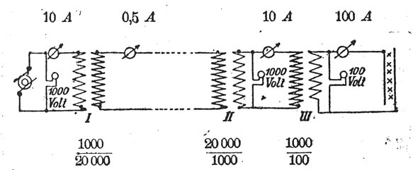
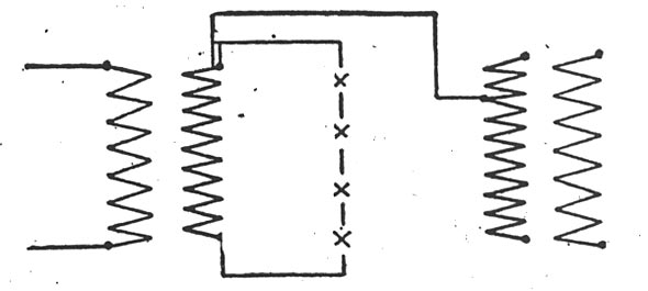
The apparatus employed in the lecture room consisted of three converters of different construction, but of an even capacity of 10,000 watts; a group of 200 incandescent lamps (10 candle power, 120 volt) connected in series, and another group of 200 lamps (16 candle power, 120 volt) connected in multiple. In addition to
| |||
| Fig 6. Experiments With High Tension Currents at Berlin. |
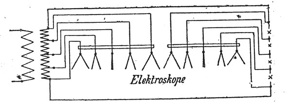
this there was a complete set of instruments for indicating the current, electromotive force, etc. A 1,000 volt, 10 ampere, Siemens & Halske alternating dynamo supplied the current. This machine was located at the factory, whence the current was carried for a considerable distance to the club-room. Copper conductors of a carrying capacity equal to No. 12 B. and S. gauge, supported by oil insulators, Fig. 1, were used. The wires were joined to converter No. 1, Fig. 2, and the dynamo current of 1,000 volts and 10 amperes was transformed into 20,000 volts, also 0.5 ampere. Through converter No. 2 the tension was again reduced to 1,000 volt, and through converter No. 3 to 100 volts and 100 amperes. At this pressure, 100 volts, the current was fed to the second group of lamps, supplying the 200 16 candle power, 100 volt lamps in multiple. Volt and ampere meters indicated during the display the exact condition of the current, and also the loss of energy in converting. As one experiment the current was taken from the secondary coil of converter No. 1, with a tension of 20,000 volts, and was carried through a fine wire to the first group of 200 lamps (10 candle power, 120 volt) connected in series. The current consumed in these lamps proved to be only 0.3 ampere. During the experiment an interesting phenomenon was observed in the lamps. The carbon filaments in the outside lamps of the series were noticed to vibrate rapidly, the rate of vibration decreasing in the lamps toward the center of the group, where the filament remained quiet. The cause of this vibration was explained by means of an electroscope, Fig. 3. From five points of
 |
| Fig 1. Experiments With High Tension Currents at Berlin. |
the windings of the secondary coil in the converter and from corresponding points in the lamp group wires were connected to two sets of foil electroscopes supported by rods of hard rubber. The connections were such that the two terminal wires, both from converter and lamps, were joined to the two outside foils of each group, and the center wire from each side to the center foil of the electroscope, and so on. In sending a current through the converter and lamps it was found that the outside foils of both sets would diverge considerably, while the foils next to them would be less disturbed, and the foils in the center would remain uninfluenced. Dr. Koepsel explained this as a proof that there are two points in the circuit where the difference of potential between the circuit and the earth is zero, and that these points when accurately determined can be touched without feeling the slightest shock, although the current and consequently its tension is the same at any point throughout the whole circuit. In approaching the terminals the difference of potential between the circuit and the earth increases. It was found that if a body in connection with the earth was brought near the lamps the filament was alternately attracted and repelled. The vibration of the filament, however, could not keep pace with the alternations of the current; when moving at the same rate, however, the filament would sometimes-strike the side of the glass globe and break off.
The electroscope was also used in testing to ascertain the possibility of an electric charging of the iron casing of the converter, but the foils did not show any deflection and the potential did not vary from that of the earth. In considering the question of the difference of potential between the converter circuit and the earth another interesting point was brought out, A wire was connected from one of the terminals of the secondary coil of a converter, Fig. 4, to any part of eithsr the secondary or primary coil of another converter and sparks of 0.4 inch, accompanied by rattling reports, were drawn from any metallic part by means of a wire with ground connection. This experiment showed the necessity, where several converters are joined in multiple, of having all connections broken when the device is not in use.
| |||
| Fig 5. Experiments With High Tension Currents at Berlin. |
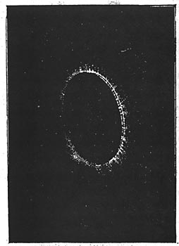
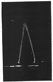
Experiments were also made showing the insulating resistance of several well-known insulating materials. A soft rubber disk of 0.04 inch thickness was placed between two brass disks each four inches in diameter. In this test the current would flow from one pole to another across the edge of the rubber disk with much sparking and rattling. It would not penetrate the rubber disk until a potential of 10,000 volts was reached. A disk of hard rubber would resist a tension of 20,000 volts without being pierced by the current. A glass disk of 0.12 inch thickness was also placed between the brass plates, and the discharge of current across its edge presented the striking effect illustrated in Fig. 5 as a photographic view of this experiment.
To ascertain the resistance of oil there was employed an apparatus consisting of two brass cups adjustable by screws and immersed in an oil bath. A current of 20,000 volts would strike through 0.12 inch thickness of oil transforming the oil at the points of contact into a cloudy mixture evidently consisting of carbonized substances.
Further experiments were made with air resistance, Fig. 6. An apparatus having ball shaped pole pieces 0.4 inch in diameter would discharge 20,000 volts through a space of 0.4 inch. With brass disks of 1.6 inches diameter, the distance for the same current would increase to 0.8 inch and with cone shaped poles of 45 degrees the space would be 1.2 inches. In this last experiment there was observed the electrical phenomenon known as St. Elmo's fire. This effect was noticed just before the actual discharge took place. The discharge between the pole pieces
| |||
| Fig 4. Experiments With High Tension Currents at Berlin. |
would assume the form of a pointed arc making a strong clattering noise, the tone of which would vary with the speed of the dynamo. The light of the arc displayed a great variation of colors, and would maintain itself even if the pole pieces were drawn apart to a distance of 4 inches. In using carbon poles the arc could be extended to 4.4 inches.
Further tests were made with samples of high insulation cables encased with lead, but without rubber for inside insulation. The cables were joined in the circuit and the lead casing grounded on the waterpipes of the room. The cables resisted 20,000 volts' pressure without sustaining any injury, while rubber insulated, lead encased cables would break down at a tension of 10,000 volts. The cuts are reprodced from the Elektrotechnische Zeitschrift.
