[Trade Journal]
Publication: Western Electrician
Chicago, IL, United States
vol. 9, no. 15, p. 222-223, col. 3,1-3
The Lauffen-Frankfort Power Transmission.
BY GISBERT KAPP.
The distance between the generating station at Lauffen and the receiving stations in the Frankfort electrical exhibition is 175 kilometres, or about 110 miles. Power was transmitted over this distance for the first time on August 25th, when the current was supplied to about 900 16 candle power lamps in the exhibition, and a few days later the output was increased to 1,100 lamps. There are
 |
| Fig. 2 |
in the exhibition two receiving stations, side by side, one for the production of power and the other for the production of light, both being connected in such a way that either power or light, or both together, may be obtained at will. The generator at Lauffen is a Brown "three-phaser," made and supplied by the Oerlikon works, and the line consists of three hard-drawn copper wires of 160 mils diameter, supported on oil insulators fixed to wooden poles 26 feet high. There have been erected in all about 3,000 poles at an average distance of 200 feet and the total weight of copper in the line is 60 tons. At Lauffen there are three transformers. One of these has been made by the Oerlikon works, and the two others by the Berlin Electricity works. At Frankfort there are also three transformers, two made by the Berlin and one by the Oerlikon works. The transforming ratio of all the six transformers is 1-160, and they are oil insulated. In the power station at Frankfort, which was fitted up by the Berlin works, the current is used for working a 100 horse power three-phase motor, designed by Herr von Dolivo-Dobrowolsky. The motor is coupled directly to a centrifugal pump, which supplies water to an artificial cascade 30 feet high. The lighting station at Frankfort has been fitted up by the Oerlikon-works, and the lamps are arranged partly on a large signboard of ornamental design in the exhibition grounds, and partly on lamp-boards, in the exhibition building, which serve for varying the load within certain limits.
Mr. Brown's generator at Lauffen is separately excited, and a rheostat is provided, so that the attendant can compensate the loss of pressure in the line by adjusting the excitation. The common junction of the three armature windings is connected to earth, and the excitation of the field is so adjusted as to obtain from 45 to 60 volts between each branch and earth, according to the amount of power flowing out of the station. The common junction of the low pressure primary circuits in the transformers is solidly connected to the common junction of the armature windings, and by means of a fuse, to the common junction between the secondary or high pressure coils of the transformers. According to the voltage of the three-phaser, the pressure between any line wire and earth is from 7,200 to 9,600 volts, and the pressure between any two line wires from 12,000 to 16,660 volts, being 2 X sin 60 deg. of that in each branch.
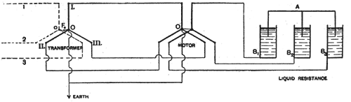
The general arrangement of the circuits from the generating station at Lauffen up to the branches which lead to the power and lighting stations in the exhibition may best be described by the diagram Fig. 1, in which G represents the generator or "threephaser," the three sets of coils being diagrammatically indicated by the three thick lines O I, O II and O III forming angles of 120 deg. with each other. The primary or low pressure coils of the transformer T, are similarly represented by thick lines, and the three thin dotted lines o1, o2, o3 represent the high pressure or secondary coils of the transformer; The generator coil O I is connected with the transformer coil O, first by the earthed wire O O, as already mentioned, and also by an insulated circuit which contains an alternate current ampere meter A1, a relay magnet R1, and a fuse, F. The other two sets of coils on the three phaser and transformer, respectively, are similarly connected. The voltage in three branches is indicated by the three volt ameters V1, V2, V3. The relay magnets are arranged for minimum and maximum current, and if the current in any of the three branches of the three phaser should fall short of the minimum, or pass beyond the maximum value for which the relays-are set, the relay in that branch cuts off the exciting current from the field of the three phaser. The voltage obtained then in the low pressure circuit at the generating station is simply that due to the residual magnetism in the three phaser, and therefore perfectly safe even in case of a short-circuit in-the primary wires. It would, of course, have been possible to so arrange the relays that in case the current in any branch becomes abnormal from whatever cause, the motive power, (in this case a 300 horse power turbine) is automatically shut down. This would, however, be a somewhat drastic remedy, especially if the disturbance is of a trivial character and capable of adjustment without stopping the machinery. As soon as the exciting power and with it the load is taken off, the turbine begins to race, and this is, of course, immediately noticed by the man in charge at Lauffen, who may then use his discretion whether he will shut down or not.
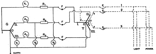
The fuses, relays, ampere meters, and voltmeters belonging to the low pressure or primary circuit at Lauffen are mounted upon one board, which also contains the voltmeter and ampere meter for the exciting circuit, and the rheostats for the latter, by which the voltage of the three phaser is adjusted. In order to compensate for the ohmic resistance of the line, the attendant works by a table giving the primary voltage corresponding to various currents, so as to keep the pressure at Frankfort constant at varying loads.
It will be seen that the arrangements of switchboard and instruments at the generating station are of the simplest possible character. In the high pressure or secondary circuit there are no switches, but merely three fuses, F1 F2 F3, as shown in the diagram. To make a fuse for 10,000 volts is not an easy problem, but it has been solved by Ferranti and others, and any of the existing forms of fuses might have been accepted for Lauffen. Since it is, however, the intention of the two firms who have carried out this transmission plant to work later on at double the present pressure (by using two transformers at each end with the thick wire coils in parallel and their thin wire coils in series) it was thought safest to arrange the fuses in such a way that there can be absolutely, no doubt as to their satisfactory working even at 20,000 or 30,000 volts. The method of mounting fuses on a board inside the station has, therefore, been abandoned, and the fuses have been placed outside, where they form part of the line. As already mentioned, the line wires are 160 mils in diameter. Close to the generating station there is a short piece of line in which each of these circuits consists of a pair of copper wires of only 6 mils diameter, and about 8 ft in length. There are two posts placed that distance apart to which the line wires are shackled, and the fuse wires serve to bridge the space between the posts. To facilitate the renewal of the fuses the posts are provided with steps. This provision is necessary because the line is at Frankfort frequently short-circuited on purpose to advise the man in charge at Lauffen that he may shut down. For this purpose there is suspended over the three line wires at the exhibition an angular stirrup or bridge of iron, which can be lowered by a cord so as to make metallic contact between the three wires. The fuses at Lauffen are thereby melted; and the man in charge stops the machinery. Telephones are then switched on at both ends, and the line wires are used to speak between the two termini. As long as the stirrup is on the wires in the exhibition, it is perfectly safe to use the telephone, even if by some mistake the machinery at Lauffen were started while a person is at the telephone. The only effect in this case would be to immediately melt the fuses again, and as their replacement gives some additional trouble to the man in charge, he will in his own interest take care not to start the machinery before the appointed time.
It remains yet to describe the provision made to guard against accidental injury to life or property in case one of the line wires should break and fall to the ground, or an earth should occur on the line through some other cause. As will be seen from the diagram the common junction O of the thick wire coils of the transformer at Lauffen is joined by means of a fuse Fo with the common junction O of the thin wire coils. The electrical center of the whole system is, therefore, permanently connected to earth. Suppose now that the line wire I should break at any point between Lauffen and Frankfort and fall to the ground, the broken end will make earth, and the corresponding fuse Fo in the line at Lauffen will go. Possibly the junction fuse Fy will go. The line I is thus cut out. In all probability the fuse in the low pressure
 |
| Fig. 1. Lauffen-Frankfort Power Transmission. |
circuit I will also melt; but should this not be the case, the current in this branch will be very much reduced, and set the relay R1 in action, whereby, as already explained, the excitation is cut off, and the dangerous pressure is immediately taken off all the three line wires.
We have yet to describe the general arrangement of the circuits in the power station at Frankfort, Fig 2. The "primary and secondary of the transformers (of which only one is shown, the other being a spare transformer at present) are again earthed at their electrical center, and the same remark holds good for the field and armature of the motor. The latter is shown diagrammatically in the same way as if it were a transformer, though this representation is not quite correct. The armature and field coils do, of course, remain in the same relative positions to each other, but for the sake of simplicity the diagram may be accepted as sufficient for our purpose. In reality, the field revolves with a greater speed than the armature, the difference in speed or magnetic slip producing the electromotive force in the armature. Now the torque of the motor is proportional to the strength of the armature current, which latter increases with the electromotive force, and, therefore, with the magnetic slip. If the magnetic slip were zero, that is, if the armature revolved with the same speed as the field, there would be no electromotive force in the armature coils, and, therefore, no current and no torque. A motor of this class can, therefore, not run synchronously, but must run the slower the more the load is increased. The variation in speed between full load and no load can, however, be made as small as desired by the simple expedient of using an armature of low resistance, so that even a slip of 5 per cent. or 10 per cent. shall produce the maximum current required at maximum load. In this respect the three-phase motor is identical with an ordinary continuous current motor with constant field, since also in this case the speed of the armature decreases as the load increases. To obtain more or less uniformity of speed is, therefore, simply a question of the amount of iron and copper which with the designer chooses to employ for a given output; but it should be remarked that by increasing the section of the armature conductor's so as to get very little magnetic slip, there is danger of producing a machine which will not readily start at full load. The reason is obvious. A very low armature resistance means an enormous armature current at the moment of starting, when the magnetic slip is 100 per cent. Now, this enormous armature current reacts very strongly on the revolving field, which is, so to speak, blown aside by the ampere turns in the armature. This may, at first sight, seem a very serious drawback to the three-phase motor, but Herr von Dobrowolsky "has hit upon a very simple and ingenious remedy. Instead of short-circuiting the armature coils at starting, he inserts into each of the three branches a liquid resistance, consisting of an iron vessel filled with an alkaline solution, into which an iron plate can be dipped to a greater or lesser depth. The three vessels, B1 B2 B3, are insulated from each other, but the three iron plates are joined by a metallic bridge A. At starting the plates are immersed only slightly, and the resistance which is thereby interposed in each of the three armature circuits, prevents the creation of abnormally strong armature currents, which would otherwise blow the field aside. As the motor gathers speed the plates are more and more lowered until the whole of the liquid resistance is short-circuited, and the motor works without external waste of energy. As regards the question of efficiency, no definite data are, as yet available, since the commission has not yet begun to make its measurements. If we may judge from the absence of heating, vibration, noise, and the general sweetness of the running of this motor, there is every reason to hope that the efficiency will be as high as with a direct-current motor of the same size. A rough test, which the writer was permitted to make on a three-phase motor of 2 horse power gave an efficiency of 82 per cent.
. From the London Electrician.
