[Trade Journal]
Publication: The Electric Telegraph
London, England
p. 187-195, col. 1
The sap ingredients being the prime movers in the rotting of dead wood, the idea has occurred to put up insulators on the stems of living trees a method which has been found to answer well in Switzerland, America, and in some parts of Germany, where trees are to be found at convenient distances. The only drawback to this system is, the violence with which trees are sometimes moved in heavy storms. To obviate this difficulty, Lieut. Col. Chauvin has constructed a swinging insulator, which will be described afterwards.
Wooden posts invariably decay first at the ground level "the wind and water line"where the surface is moist and in contact with the air. A method of retarding the decay by sheathing the post at this part has been tried in India with comparative success, the lower end, to a certain height above the ground, being covered by an iron casing. In Bengal such a line was erected, the posts being of large bamboo canes and the protection of the lower parts cast-iron sockets.
This brings us very near to a suggestion which has been much advocatedthat of dispensing with wood, and con- constructing the posts entirely of iron, whose durability is so superior. The greater cost of such posts is the only objection to them.
 |
| Fig. 97 |
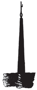
Pillars of stone, or mason's work, would undoubtedly not only last longer, but would be less liable to accidents by violence of the weather. Such supports have repeatedly been constructed, but their cost has always been a bar to their further employment. In India, in the early days of telegraphy, many such pillars were erected, and in 1852 a line from Treviso to Tagliamento was entirely supported by obelisks 4-1/2 metres high, as shown in Fig. 97. In Switzerland they have begun in good earnest the use of iron posts, the line from Olten to Sissach, lately erected, being supported entirely by iron posts. In Prussia also the necessity has been fully comprehended of discarding wood and taking to some more durable material. Mr. Borggreve has employed, on the line between Gera and Weissenfels, a pillar constructed of a wrought-iron tube, 1-1/2 inch diameter, fixed with lead into a socket on the top of a freestone pillar, 6 feet high and 8 inches square.
The iron post of Mr. W. Siemens is coming Very generally into use abroad, and will no doubt find employment in England also, when the necessity of a durable post becomes thoroughly appreciated.
 |
| Fig. 98 |
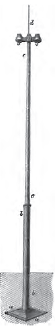
This post is formed of two tubes, one set upon the other, and the bottom of the lower one made fast to a bent plate of iron buried in the ground. One of them is shown in Fig. 98. The base consists of one of Mr. Robert Mallet's patent buckled wrought-iron plates, 1 foot 9 inches square, bent in a dish form. The buckled plate a a is secured by four bolts to the socket b b a cast-iron cylindrical tube 7 feet long and 4 inches outside diameter. Near the top, inside, the socket is furnished with a flange, upon which the bottom of the upper or main-post, as it is called, rests. This upper post, c c, is of wrought iron with welded joints; it stands 12 feet high out of the socket, and is somewhat conical. At its upper end an iron ring is welded in to carry an iron rod,d, 20 inches long, forming the lightning guard. The stretching posts are of the same height, but of larger diameter and stronger than the ordinary ones.
Mr. Siemens' post derives much of its merit from the role played by the buckled plate at the bottom. These buckled plates are things of great engineering utility. They are squares of sheet-iron, which Mr. Mallet by a simple process presses into a form very slightly different, but endows them with a strength immensely superior; so strong indeed are they that if one of these posts were pulled up bodily out of the ground, it would bring up the superincumbent ground with it, and the buckled plate would not be deranged unless the bolts gave way; while the same piece of iron, as a simple sheet, would bend' under a much less weight, offering no resistance worth speaking of against the strain.
There can be little doubt that, in course of time, only metal posts will be employed, on account of their superior durability, solidity, and freedom from damage by accidents. In some climates wooden posts require to be renewed every two or three years, and, in the most favourable, rarely last over six years; while an iron telegraph post is as durable as a lamppost, and would certainly last ten times as long, and not cost five times as much as a wooden one; so that in the end an immense saving would be effected by their employment, although the first cost is so much greater.
103. Line Insulators.Cook's insulator was the first used in England. It consisted of a body of earthenware the size and form of an egg, slightly flattened at the ends: the wire was passed through a hole in its longer axis.
 |
| Fig. 99 |
Bright's insulator, used by the Magnetic Company, consists of a porcelain bell, Fig. 99, provided at the top with a notch for the reception of the line-wire, which is secured by a pin in a hole at right angles to it. One end of a bolt is cemented into a hole in the under-side of the insulator-cap, and by this it is secured to a cross-bar of wood screwed on to the post.
When a post has to carry a number of wires, the cross-bars are of different lengths, the longest being at the top, and each succeeding one shorter than the one above it, that, if a wire should break, it would fall clear of the insulator-caps beneath it.
 |
| Fig. 100 |
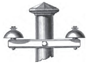
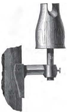
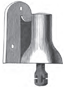
In 1852, Siemens and Halske invented their bell-insulator, which is the strongest and one of the best-constructed supports. It consists of a cast-iron bell, a a, Fig. 100, with a flange, b b, by which it is screwed against the post. Inside the bell is cemented a porcelain cup, c c, ribbed inside and out to give a good hold to the cement. The cup, c c, in turn, carries the stalk or hook, d d, which supports the line-wire. The parts are put together, while hot, with a cement composed of sulphur and oxide of iron. As a further mode of insulation, the iron stalks or hooks are covered with vulcanite before being cemented in ; sometimes the porcelain cup is replaced by a cup of vulcanite. These insulators are a little heavy, but their superior solidity and insulation is ample compensation, the iron cap forming at once a perfect protection against injury and a screen against the deposit of dew on the porcelain.
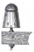
In 1856 Mr. Clark patented an insulator in which he increased the length of surface of the porcelain over which the current escapes, without increasing its section. He attained this by a double bell formed in one piece. The insulator is supported by a stalk, D, Fig. 101, cemented into the interior of the inner cavity; the line-wire is carried through a deep groove on the top, and is tied to the bell by a binding wire.
 |
| Fig. 101 |
Lieut.-Col. Chauvin, Director of Prussian Telegraphs, has adopted this style of insu - lation for many of the lines under his charge. He has also made numerous experiments on the most favourable proportions between the length and section of the cups, and has given them a form differing slightly from Mr. Clark's only in an increased depth and narrowness of the inner cavity, by which the deposit of dampness from the atmosphere is still further guarded against, as well as the sudden cooling of the insulator bell.
 |
| Fig. 102 |
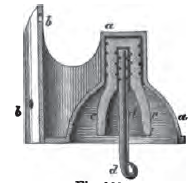
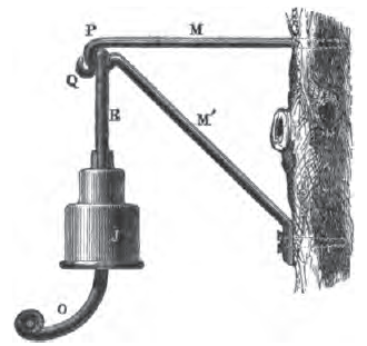
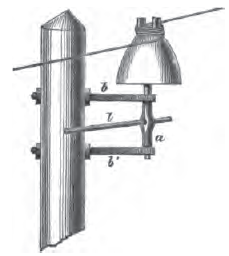
Lieut.-Col. Chauvin has also constructed an insulator for attaching to the stems of living trees when these are used instead of posts for the support of telegraph lines. The insulator is hung upon a hook, free to swing about; and the stalk, or wire-carrier, bent in a curve away from the stem of the tree, that, when the latter is deflected by the Wind, the line-wire, in swinging, may not come into contact with it. The hook Q, Fig. 102, held in the loop P of the bracket M M', is twisted so that, in case of a sudden jerk, the line cannot be thrown upwards and the insulator disengaged from the bracket. The carrier o is also bent over the wire, to prevent the line jumping out. The bracket is formed so that the insulator hangs quite free of the stem.
 |
| Fig. 103 |
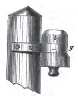
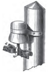
The Spanish insulator consists of a porcelain bell, b, Fig. 103, supported by a strap of hoop-iron fitting into the groove g, and screwed to the post. The line-wire is carried by a stalk cemented into the inner recess of the bell. The chief merit of this insulator is its cheapness. In climates like that of Spain it answers well enough, but would be utterly useless in England, where the atmosphere is always charged heavily with water vapour, which, condensing on the surface, would soon occasion a material loss of current.
 |
| Fig. 104 |
Varley's insulator is that most commonly employed in England. It consists of two separate red-earthen ware cups, a and b, Fig. 104, cemented together with sulphur. The outer cup a is provided with a groove to which the line wire is bound ; in the recess of the inner cup b, a wrought iron bolt, c, is cemented, by which the insulator is attached to the bracket d, on the post. A further insulation is obtained by coating the stalk with vulcanite. The rim of the outer cup b is rounded off inside. The purpose of this is to avoid the sprinkling of the interior with rain-water, when a drop, hanging upon the bottom rim, is blown off by the wind. When a strong current of air separates a drop of water from a sharp corner, the drop is never carried bodily off, but bursts in the direction of the current. With the form given to the rim by Mr. Varley, however, when a drop happens to hang on that side from which the wind comes, it is driven a little way up between the two cups, and does not burst.
104. Stretching Insulators.The weight of the wire in the space which it makes between two posts, assisted by the occasional pressure of the wind against it, causes it, after a time, to stretch and curve lower towards the earth. When a single wire is suspended, this is of no importance; but when several wires are supported between the same posts, by stretching, they are in danger of touching each other and causing interruptions of the service. To avoid this, the line is provided at intervals with insulators of larger and stronger make than the ordinary ones, to which the wire is made fast, thus giving, at intervals of half a mile or so, fixed points to the suspended line, while the intermediate insulator hooks serve only to support it, without resisting any horizontal strain.
 |
| Fig. 105 |
Siemens and Halske's stretching insulator is made with a stronger and larger cast-iron bell than the ordinary one. The porcelain boss or cup carries a stalk with two notches (Fig. 105), through which the wire is drawn and wedged on each side, leaving a loop between them. In cold weather, when the line contracts, this loop allows the wire between the posts to be slackened, and also, in case of a rupture, gives sufficient spare for making a joint.
 |
| Fig. 106 |
Kohl's stretching insulator is shown in Fig. 106. It is cemented upon the vertical bar or stalk a in its centre, and is turnable in the supporting bracket b, b, with the aid of a lever, I. The top of the porcelain bell is cut out in a deep groove, into which the line wire is placed and then bound up tightly by turning the lever. This insulator finds employment principally in Germany.
 |
| Fig. 107 |
Another method of stretching with the insulator itself is by means of a wrought-iron winch, w, attached to the stalk, as in Fig. 107. The ends of the line wire on each side are passed through holes in the two drums d d', and wound up tightly, the drums being prevented from running back by clicks and ratchet-wheels on their axles.
