[Trade Journal]
Publication: The Electrical Transmission of Energy
New York, NY, United States
p. 68-85
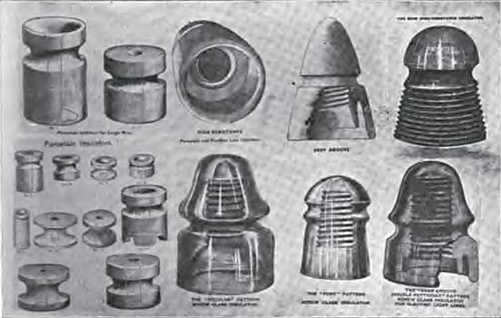
44. Insulators. The number and form of line insulators, together with the materials proposed for their construction, have been legion. In this country glass is almost universally used for telegraph and telephone work, and for the latter the tendency has been to make the insulator as small and light as possible. In England, however, the porcelain insulator is the most common, the difference in climate fully accounting for the English preference. As an insulating material, glass has several disadvantages. It is considerably more hygroscopic than porcelain, readily condensing on its surface a film moisture which rapidly lowers its insulating qualities. It is very brittle, decidedly more so than porcelain or earthenware. While blown glass is better in every respect than that which is cast, it is so much more expensive that molded insulators are almost universally used. The great advantage of the glass insulator lies in its transparency, which prevents the formation of cocoons under the petticoats of the insulator, that have a very marked effect in lowering the resistance of lines. Ebonite and india-rubber have been used to quite an extent for insulators; but as they quickly roughen by exposure to the weather, and are considerably more expensive, their use has been almost exclusively confined to electric railway work. Brown stoneware forms an excellent substance for insulators, as it is strong, cheap, and durable, seldom cracks, and its color makes it inconspicuous. Thoroughly vitrified porcelain is probably the best insulator on the whole, and is used almost exclusively in England and on the Continent. The surface resists the formation of film moisture, and is easily washed clean by rain. The more common forms of line insulators are represented in Fig. 22 (p. 69).
| |||
| Fig. 22. Specimen Insulators. |
45. The Value of Insulators. Many experiments have been made to determine the value of poles, cross-arms, and insulators, to maintain line insulation. One test made on a telegraph line extending from New York to Boston, gave a result showing an insulation resistance of about 6,000 ohms per mile.
·
·
When the same insulators were carefully cleaned, their insulating power was raised to about three times the above value. These figures give in a striking manner the loss in insulation by exposure to smoke and dirt.
Some more recent experiments have been made by taking 50 of each of the typical forms of insulators, mounting them in the ordinary way, and exposing them for some months to the action of the weather, the leakage over the insulators being carefully determined by the best-known electrical instruments, while a constant meteorological record was kept of the variations in atmospheric conditions. These experiments covered a period of nearly 150 days, observations being made at least once a day during the time. About half of the observations were made in clear weather, one-fifth in fair weather, 18% in cloudy weather, and 12% in foggy or rainy weather. The general results indicate that the greatest losses in insulation occurred daring foggy or misty weather, when the insulators became coated with a thick beady film of moisture. During a heavy rain the insulation was somewhat higher; and after a storm, when sufficient time had elapsed for the drying of the insulator, the resistance of the line was considerably improved, owing to the cleaner condition of the insulating surface. The open double petticoat insulator was found to dry more rapidly than the close single petticoat; but during actual rainfall the loss in insulation of the double petticoat form is greater and more rapid than that of the single. In fine weather the large sizes of each form indicate parallel results, though the double petticoat form gave a much higher resistance than the single form of corresponding size. The true value of any form of insulator can only be properly computed when a consideration of the actual size of the insulating-bell has been eliminated, and attention concentrated entirely upon the possible cross-section of conducting material in the shape of moisture or dirt which may be deposited upon the exterior of the bell. To determine this, it is necessary to ascertain the mean circumference of the insulating material, divided by the conducting length between the point at which the wire is secured and the point of attachment of the insulator to the cross-arm. From this, the possible amount of conducting film may be determined by multiplying the mean circumference by the distance over the insulating surface, and evidently a form giving the greatest length in proportion to the mean circumference will have the highest insulating powers. 46. It is necessary to have the insulators closely and accurately fitted to the pins, and to plan the point of attachment of the wire as low down as possible, in order to give the smallest leverage upon the pin. With the growth of the transmission line the pin question has become of much importance. Mr. R. D. Mershon recently proposed the following mechanical specifications, (*Trans. A. M. Inst. E. E., vol. XX., p. 415.) which probably represent good engineering opinion as to dimensions of wooden pins:
Threaded End.It is proposed to make the diameter of the small end of the pin 1 inch; the length of the threaded portion 2 1/2 inches ; and the diameter at the lower end of the threaded portion 1.25 inches, so that the threaded portion will taper from 1.25 inches to 1 inch in a length of 2 1/2 inches. The threaded portion of the insulator should have the same dimensions and taper as that of the pin.
Shoulder. It is proposed to make the shoulder 3/16 inch on all pins. That is, the diameter of the pin just above the cross-arm will be 3/8 inch greater than the nominal diameter of that portion of the pin in the cross-arm; it is proposed to carry this diameter 1/4 inch above the cross-arm before tapering the pin.
Dimensions in Cross-Arm.It is proposed to make the diameter of that portion of the pin in the cross-arm, just below the shoulder, 1/32 inch less than the diameter of the hole in the cross-arm, and at the lower end of the pin 1/16 less than the diameter of the hole in the cross-arm. It is proposed, also, to designate this portion of the pin as having a nominal diameter equal to that of the hole in the cross-arm into which the pin fits. Therefore, that portion of a pin which is to fit a 1-1/2-inch hole in a cross-arm will have a nominal diameter of 1-1/2 inches, but will have an actual diameter just below the shoulder of 1-15/32 inches, and at the lower end of the pin of 1-7/16 inches.
Thread.It is proposed to use on all pins a thread having a pitch of 1/4 inch, or four threads to the inch.
Designation.It is proposed to designate that portion of the pin above the cross-arm as the "stem" of the pin ; that portion in the cross-arm as the "shank " of the pin. It is proposed to designate a pin by the length of its stem, i.e., a pin whose stem is 5 inches long will be designated as a "5"-inch pin, one 6 inches long as a "6"-inch pin, etc.
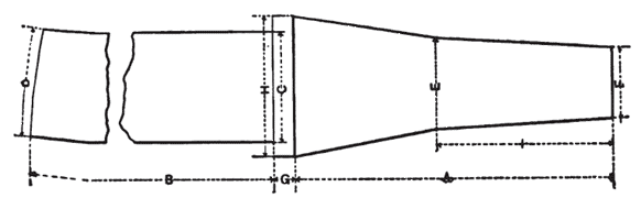
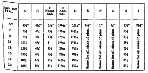
47. Dimensions of Standard Pins.The following diagram (Fig. 23) and table give a number of sizes of pins, and their dimensions, which it is proposed to make standard. The diameter of the shank has in each case been fixed by making it approximately equal to (slightly larger than) the diameter of the theoretical pin corresponding to the length of the stem of the pin in question. The headings of the columns of the table refer to the lettering of diagram, which is a full-size unthreaded 5-inch (proposed standard) pin.
 |
| Fig. 23. |
 |
| Table |
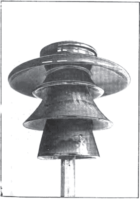
48- To properly insulate a modern transmission line where cables may aggregate many hundreds of thousands of circular mils, carrying a potential of from 50,000 to 80,000 volts, taxes to the utmost all the resources of both electrical and mechanical engineering. From a mechanical standpoint the stresses both vertical and horizontal that the heavy wire or stranded cable necessary to a line transmitting hundreds or perhaps thousands of horse-power, are of no mean order, Particularly when complicated with wind and snow loads, whose effect it is exceedingly difficult to calculate. All materials which have sufficient electrical resistance to be used in building insulators are mechanically weak and brittle, so that the engineer must not only deal with stresses of magnitude and of indeterminate amount, but is compelled to use almost the worst possible material in an attempt to resist them. Nor is the problem an easy one from the electrical aspect. Lines are actually working at 40,000 to 60,000 volts normal pressure, superimposed upon which is the possible exaltation of potential due to harmonies produced by the properties of the line, or of the translating devices with which it may be loaded, or initiated by the sudden opening or closing of switches, an accidental short circuit, or other contingency. For heavy work glass and porcelain are the only materials now in current use, and opinion is divided as to which of the two is preferable. In a general way porcelain is admitted to be the best, provided it is good, but it is equally conceded that it is comparatively much more difficult to secure a good porcelain insulator than to get a good glass one. So, while it is intrinsically the better material, manufacturing difficulties are bringing glass more and more into use. Much ingenuity has been expended in the design of insulators for large transmission lines. Figs. 24, 25 and 26 show types that have been widely used, particularly with high voltages. Essentially insulators consist of three parts: an umbrella, an inner core that forms a petticoat, and a pin-shield. The umbrella carries the line wire, which is held in a groove on the top and tied thereto in the usual manner. The umbrella is often provided with a rim surrounding its edge, called an "eave," as in Fig. 27, which serves to collect all the water which may collect on the insulator, and prevents it from either following the under side of the umbrella or being blown against the petticoat or pin-shield. A spout shown conveys away the drainage in any predetermined direction. The model of Fig. 25 is designed for 60,000 volts, while that in Fig. 26 is for 80,000 volts.
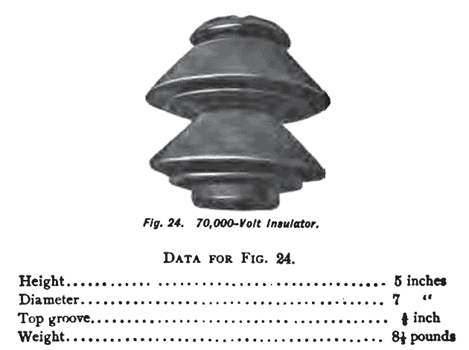 |
| Fig. 24. 70,000 Volt Insulator. |
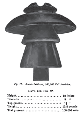 |
| Fig. 25. Double Petticoat, 100,000 Volt Insulator. |
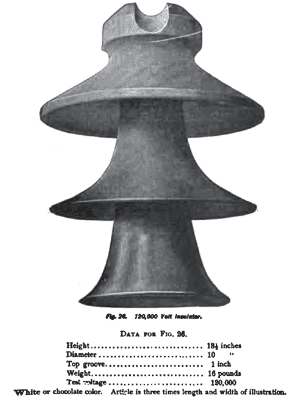 |
| Fig. 26. 120,000 Volt Insulator. |
 |
| Fig. 27. Strain Insulator. for Corners. |
The designs of Figs. 25, 26, and 27 are built of porcelain. In Fig. 28 a combination insulator is shown which can be made of all porcelain, all glass, or either the petticoat or the umbrella can be made of glass or porcelain, and combined as may be desired.
 |
| Fig. 28. Glass Petticoat Insulator |
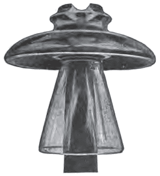
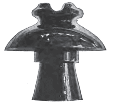
Figs. 29 and 30 are illustrations of somewhat similar designs, but smaller in size and lighter, and intended to work at from 30,000 to 80,000 volts.
 |
| Fig. 29. - 80,000 Volt Insulator. |
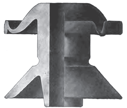
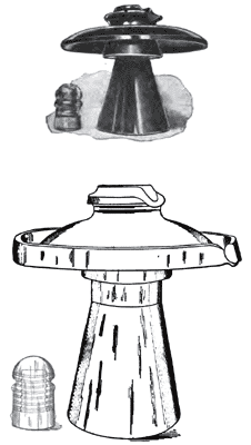
In view of the imperfections to which porcelain is liable, and to prevent excessive losses in burning, which are often occasioned by differences in thickness between the body of an insulator and the thin edges of the petticoat, the artifice of making an insulator in sections, as shown in Fig. 31, is often adopted. As indicated, the insulators consist of three independent concentric bells designed to fit one on top of the other. Each bell is moulded and burned separately, and then tested, imperfect ones rejected; subsequently the three bells are coated with a fusible glaze and fired a second time, thus uniting all three into a single insulator. This illustration also shows a form of pin which is particularly desirable for transmission lines. The pin consists of a steel bolt from 1/2" to 3/4" in diameter, depending upon size of wire which it is to support. Upon the top of the bolt a porcelain base is mounted, and above that a locust or oak block, upon which the proper screw-thread is formed for supporting the insulator. Evidently this pin may be made of any desired strength and yet necessitate but a relatively small hole in the cross-arm. The porcelain base provides an insulating incombustible and indestructible base, while the wooden thread secures sufficient elasticity to enable the pin to fit the thread of the insulator without being so rigid as to injure the vitreous material.
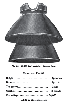 |
| Fig. 30. - 40,000 Volt Insulator. Niagara Type. |
The type of glass insulator shown in Fig. 32 is a favorite with the electrical railway transmission lines, and is used extensively in Ohio and Indiana on the Interurbans. The line is bare copper from No. 4 to 00, depending on the power to be transmitted, and is tied in a groove in the top of the insulator. Insulators of this kind are excellent for from 15,000 to 20,000 volts.
Much difference of opinion has existed as to the desirability of a multiplicity of petticoats. On one side several petticoats are claimed to give a longer surface over which leakage must take place. To offset this there is a greater surface for the collection of moisture and dust, shorter air space, and greater manufacturing difficulties. Latest designs incline to a large umbrella and very long pin shield, as is by the insertion of an ordinary telegraph insulator.
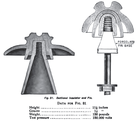 |
| Fig. 31. Sectional Insulator and Pin. |
| |||
| Fig. 32. - 20,000 Volt Railway Transmission Line Insulator. |
 |
| Fig. 33. Umbrella and Pin Shield Insulators. |
| |||
| Fig. 34. A Modern Transmission Line. |
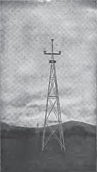
The curves of Table No. 35 (in Pocket) are interesting, as indicating the amount of leakage in watts as experimentally determined over various kinds of insulators. These curves are also instructive, as demonstrating that the material of which the insulator is constructed is of far less importance than the shape into which the material is formed. Relatively to telegraph and telephone construction, transmission lines carry very few wires; but as these are apt to be of large size, the line stresses may be increased, while those on the individual insulator and pin are largely augmented, requiring double arming at all corners, and often in straight-line work. Fig. 34 is a typical example of the modern transmission line.
Bad insert syntax: TABLE. 35.
 |
| Fig. 35. Line-Wire Tie. |
 |
| Plate 1 - Transmission Line Insulator. 80,000 Volts Working Pressure. |
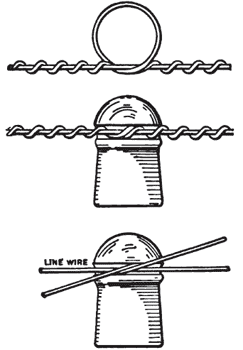
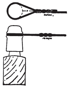
49. Tying and "Dead-Ending."To secure the line-wire to the insulator would seem a simple matter; yet to devise a tie that is secure, simple, economical, and effective has taxed the ingenuity of line men.
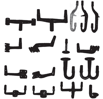
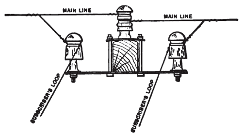
The standard method now in use is shown in Fig. 35. The line-wire is laid in the groove of the insulator, and a soft copper wire from 8 in. to 24 in. in length, and from No. 12 to No. 6, depending on the size of the line wire, is placed in and around the insulator groove, in such a manner that one end of the tie-wire shall pass down over the line wire, and the other end up over it, as indicated in Fig. 35. The fastening is then completed by wrapping the tie-wire continuously around the line-wire. Much practice is needed to make this tie in the neatest and securest manner, without injury to the surface of the hard-drawn copper of the line. The strength of the insulator tie is usually supposed to be, when well made, about one-fourth to one-third of the line-wire. When a wire terminates, it must be "dead-ended," in order to secure it from falling, and transfer the tension of the wire to the pole. This is accomplished as shown in Fig. 36. The line-wire is carried entirely around the groove of the insulator, and either wrapped about itself, or fastened with a Mclntire joint. In order to give service at any point on a line, the necessary circuit must be carried into the premises of the customer. To effect this the line is usually dead-ended on the nearest pole, and a loop carried to the building to be served. For this purpose brackets are necessary; the best forms for the multitude of cases that may arise in practice being indicated in Fig. 37, while in Fig. 38 the bracket in place is illustrated. For a grounded line, a single pin-bracket is sufficient, for only one wire is carried off of the pole. For a metallic circuit, or for a loop in a series circuit, a double pin-bracket is required. A favorite form, with the method of application, is sufficiently clearly illustrated in Fig. 38 to need no additional explanation. Other forms of double brackets are seen in Fig. 37.
 |
| Fig. 36. "Dead-Ending." |
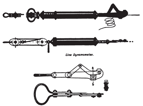
50. Stringing Wires. After the poles and insulators are set, the erection of the wire is to be undertaken. When there are a very few circuits, it is common to mount one or more reels containing the necessary wire upon a cart, and then to drive the cart slowly along, hoisting the wire up to its appropriate place as fast as the cart passes each pole. If a heavy line is in process of construction, the work can be greatly expedited by the use of what is termed a "running-board." A number of reels of wire, usually ten or more, are mounted upon spindles, and a piece of wood, practically the same as a cross-arm, is arranged, to which ten or more wires are attached. Horses are then harnessed to the cross-piece, as the running-board is termed, and as they "walk away," dragging the running-board after them, the wires are paid out from the reels, and, passing over the appropriate cross-arm, may be immediately secured to the insulators by linemen stationed for the purpose. After the wire upon all the reels has been run out, each wire is pulled up to its appropriate tension by means of a dynamometer, and a small portable vise, technically termed a "come-along," as illustrated in Figs. 39 and 40.
 |
| Fig. 37. Standard Brackets. |
 |
| Fig. 38. A "Loop." |
 |
| Fig. 39. A "Come-Along." |
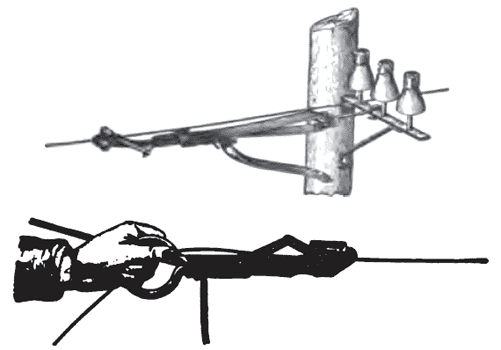 |
| Fig. 40. the Come-Along in Service. |
·
·
