[Trade Journal]
Publication: Journal of the Society of Telegraph Engineers
London, England
vol. 7, no. 22, p. 123-173, col. 1
The Sixty-fifth Ordinary General Meeting was held on Wednesday, the 13th of March, 1878, MAJOR BATEMAN-CHAMPAIN, R.E., Vice-President, in the Chair.
The Secretary read the following paper :
INSULATORS FOR AERIAL TELEGRAPH LINES.
By JOHN GAVET, Member.
In venturing to bring before the Society the question of insulators for open-air lines, the author rather desires to draw general attention to the whole subject than hopes to be able to impart any new facts. That there is wide room for improvement in our present standard of insulation is, it is believed, generally admitted, and, inasmuch as it is frequently simply necessary to let it be clearly understood that a want is felt, in order to stir up inventive minds to satisfy that want, it is thought that some of the facts set forth below, and the valuable discussion that generally follows a paper on a practical subject of this character, may result in drawing attention more fully to the whole question.
In dealing with the subject, it will perhaps be advisable to consider, first, the principles which should guide us in designing or selecting an insulator; and these may conveniently be dealt with under two heads, viz.: The material of which the insulator is to be made, and the form to be given to it.
First, the material.Its electrical resistance should be as nearly as possible infinite, for, obviously, unless it possesses this quality it will be useless as an insulator. It should be homogeneous throughout its substance. It should not be porous, for if it be so, it will inevitably absorb moisture; and whatever be the specific resistance of the material itself, it will become a more or less good conductor when saturated with water; and the difficulty of wholly expelling moisture, when once absorbed, is perhaps not always fully appreciated. An illustration of this is given further on. It should be susceptible of having a high polish, or a smoothly glazed surface, in order to retard accumulations of dirt and dust, and to admit of all such accumulations being readily removed, partly by the natural action of rain-showers, and thoroughly when needed by hand-cleaning. It should not be subject to deterioration, either on its surface or internally, through atmospheric or electrical causes, through variations of temperature, through frost, through the action of acids and salts held in suspension, or through other like causes. It should be readily moulded into any form which it is desired to adopt, and it should retain that form unchangingly. It should have as slight an affinity for moisture as possible, so as to diminish the formation of conducting films over its surface when the atmosphere is saturated. Its tensile and compressive strength should be sufficient to admit of its withstanding the maximum strains to which it is likely to be exposed in practice, without deterioration of any kind, and lastly its toughness should enable it to withstand with impunity ordinary blows and the rough usage to which engineering materials are always more or less exposed.
The evil of porosity in any material employed for insulating purposes is doubtless well appreciated, but it may not be so generally understood how difficult it is to eliminate moisture once it has penetrated the pores of an insulating substance. The following experiments bear on this subject. Following some published results by Du Moncel, on the polarization and conductivity of minerals, certain experiments were made by the author for Mr. W. H. Preece, with the object of ascertaining how far the conductivity arose from absorbed moisture and how far from the materials themselves. The following specimens were selected, cut evenly and ground down smoothly on two opposite faces. They were then carefully washed to free them from grease, oxide, and other possible disturbing elements, laid on a clean glass plate, and left untouched, in an ordinary room without fire, for three days, to allow them to dry.
The stones experimented on consisted of the following:
1. Bath oolite.
2. Alabaster.
3. Reddish lias.
4. Red sandstone.
5. Reddish lias.
6. Bridgend lias.
7. Common sandstone.
8. Pennant sandstone.
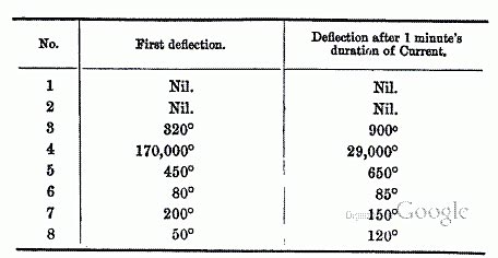
On testing them with a Thomson's galvanometer, having a constant of 148° with one cell through 10 megohms, at the end of the three days all the specimens gave full deflections, with 289 cells and 1,000 shunt, platinum electrodes being attached on either side of each stone. They were all then exposed to heat, by suspending the glass plate which held them two inches above an ordinary closed iron stove, which was kept intensely heated for a period of six hours. The temperature of each stone, having then for a considerable time been such that it would not bear touching with the hand, readings were again taken, with the same constant and battery power, the following being the results:
|
A further exposure in the same manner, to similar heat, on tho following day for eight hours, resulted, at the end of that time, in the following readings:
|
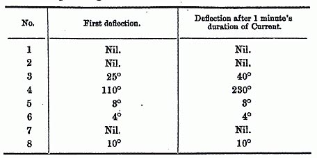
The specimens were then laid on a sheet of clean iron, directly on the top of the stove, so as to increase the temperature still further, when all traces of conductivity finally disappeared, after a lengthened exposure to a temperature which sufficed to decompose the alabaster. Other specimens of different stones subsequently experimented with acted in a similar manner. It may therefore safely be assumed that no ordinary natural temperature, in this country, would suffice to wholly expel absorbed moisture from a porous substance.
In practice, but few materials have been employed in the manufacture of insulators. They may be said to have been limited to glass, porcelain, earthenware, ebonite, and wood saturated with insulating compounds.
Glass, originally one of the first materials used, was rejected in this country, on account of its readily condensing films of moisture over its surface, and also because of its brittleness and its tendency to fracture under variations of temperature. It is now, however, used in America and Switzerland to a considerable extent, and some of the results obtained with it are said to be good. It possesses, in a high degree, many of the requisite qualities of a material for an insulator. Its electrical resistance to direct conduction is almost infinite. It is non-porous, homogeneous, highly polished on its surface, readily moulded into any given shape, and easily manufactured of a given quality, but unfortunately those objections already mentioned were found so strong as to lead to its entire rejection in England.
Porcelain has perhaps been more widely adopted than any other material, and, if properly selected, well manufactured, thoroughly burnt, so that, a partial vitrification having taken place through- oat, it becomes homogeneous and non-porous, it probably affords the best material hitherto used. If of really good quality, it satisfies many of the conditions laid down, its principal defect being its brittleness. Of course much depends on the selection of the ingredients of which it is made and on the care devoted to its manufacture, but even when this is observed to the utmost, the insulators made of it should be subjected to searching tests before being accepted.
According to the description of clay used, and the different proportions in which this is mixed with the powdered flint and other materials employed, will the porcelain be hard or soft The proportions used are generally trade secrets, each maker having his special formula for mixing. That manufactured in Prussia, the Berlin porcelain, is of a very fine description, extremely hard, and is much liked by some.
In this country a softer porcelain generally is used for insulators. It is probable that the harder German porcelain gives a higher specific resistance than English porcelain generally, but the latter can be selected so as to give such a high result as to be practically infinite, in comparison with the absolute resistance of an ordinary insulator, which is comparatively low owing to surface leakage. There is no evidence to show that the softer qualities deteriorate more rapidly, under atmospheric or electrical influences, than the harder ones.
The final test for porcelain, as for any other material used for insulators, is of course the electrical one; for invisible fissures, porosity, or other imperfections, are thereby detected; but a careful examination of the fractured sections of an insulator will generally give some idea of its quality. If properly made up and sufficiently fired the fractured surfaces exposed will be more or less conchoidal, smooth, even, and homogeneous in appearance. Any departure from this evidently indicates imperfection.
I am indebted to Mr. Bell, the superintendent of the factories in the Telegraph Department of the Post Office, who has necessarily had a wide experience in this direction, for the following brief summary of the causes of the low resistance of the insulators which are rejected after being exposed to the ordinary tests.
First. Flints not ground fine enough to make with the other constituents of the porcelain a smooth paste. The fractured section of the ware, when examined with a lens, is roughly comparable to a quarry of chalk with its intermixed flints.
Second. Insufficient firing to fuse the flux.
Third. Excessive firing, which makes the ware spongy.
It will be seen that these are merely defects in manufacture, preventable by the adoption of proper precaution; and as they are readily detected they do not militate against the use of the material itself.
Stoneware, which has been employed to a considerable extent in this country, is perhaps of a more variable character than porcelain, but if carefully selected, moulded under a considerable pressure, and well burnt, it falls very little short of porcelain as a material for insulators; and its unpretending colour appears in many localities to insure its freedom from the stone-throwing proclivities of the idle and mischievous, whilst the staring white of the porcelain appears irresistible. In respect of theoretical conditions, well selected and manufactured stoneware stands about on a par with porcelain. Many of the remarks as to the manufacture of porcelain will apply to that of stoneware.
Ebonite, which appeared a most promising material, and was at one period somewhat extensively used, failed through its rapid surface deterioration under the influence of the atmosphere. This is fatal to its employment for out-door insulation. Could this be overcome it would be a most valuable substance on account of its high insulating qualities and its small affinity for moisture, and its use would then probably admit of considerable improvements in the present standard of out-door insulation.
Wood, saturated with insulating substances, has been tried. It is questionable whether a high-class insulator could with safety be turned out of this material. It is extremely difficult to deprive a very porous and hygrometrical substance like wood of its strong tendency for absorbing atmospheric moisture, in fact it is a question whether it would be possible to entirely fill up its pores, and the freedom from malicious fracture, which its use would carry with it, would be dearly purchased at the cost of the lowered insulation which would certainly follow any failure in the attempt to render it impermeable.
In the second place we have to deal with the form of the insulator. Taking the resistance through the substance of the material selected as approximately infinite, which it would be practically in any but a defective specimen, the conductivity of an insulator arises through the deposition of a film of moisture over its surface. Now the ordinary law, that the resistance of a conductor varies directly as its length and inversely as its section will evidently apply in this case as in others, and therefore in calculating the resistance of a given insulator, or, in other words, the resistance of the film of moisture condensed on it, we have for its length the distance over its surface from the point where the wire is attached, to the point where the insulator is affixed to the pole; and for its section the thickness of the film of moisture multiplied by the mean circumference of the insulator. Assuming, therefore, that under like atmospheric conditions the thickness of the film of moisture deposited on various forms of insulators of the same material will be constant, the resistance of each insulator will vary directly as its length and inversely as its mean circumference. This law in practice applies with accuracy only to simple cylinders, for in complex forms of insulators other disturbing causes are introduced, which will appear further on.
The theoretical conditions to be aimed at, therefore, in designing the form of an insulator, may be enumerated as follows:
The maximum resistance should be obtained by any of the various means which may be suggested, viz., by increasing the length to be traversed by the current, whilst diminishing the section of the conducting film; by the retention of a dry surface on one portion of the insulator, either during heavy rains, mist, or fog, or if possible under all circumstances; by the adoption of a form that will not aid or retain deposits of dust, soot, or other materials, which if not conductors per se act very injuriously, by retaining and in creasing the thickness of the moisture films; and also one that will not foster accumulations of the cocoons of spiders and other spinning insects. The insulator should admit of its surface being readily washed, naturally by heavy downpours of rain, and of thorough cleansing in all its parts, when necessary, by the lineman who has charge of the length. The construction should be such that the partial or entire fracture of an insulator should not necessarily interrupt or materially impede the working of the line. It should admit of the conductor being readily and firmly attached to it, and should be so constructed that if a wire be broken in one span the insulators on each side of the break should retain the fractured wires, and not allow them to run back; and, finally, it should be readily attached to and removed from the supports or poles, without the aid of highly-skilled labour.
Diagram No 4.
 |
 |
In the early days of telegraphy wires were insulated in this country with short cylinders of earthenware, pierced through the axis, and supported by a ring, which fitted a groove in the circumference. Various improvements, which scarcely require further attention here, were made in succeeding years, by which the standard of insulation was gradually raised, until in 1856 Mr. Latimer Clark introduced on the lines of the Electric and International Telegraph Company the well-known porcelain invert, which may be called the parent of a whole generation of the modern form at present in use. This invert is so well known as to need but the most brief description. It consisted of a so-called double-cup insulator, of the section showed in fig. 22 (Plate 4), supported on a vertical pin, and containing a deep groove in the top to carry the conductor. These were largely used in England at the time they were first made, but they were subsequently replaced by Varley's well-known earthenware insulator (fig. 2), in which the two cups were altered in shape, prepared in separate pieces, and cemented together, so that a flaw or fracture in one would not destroy the insulating power of the whole.
In this country until recently Varley's double-cup earthenware insulator (fig. 2) and the double cup porcelain insulator shown in fig. 3 have been exclusively employed for all main circuits. For unimportant branch circuits single-cup insulators (figs. 4 and 9) have been employed, which afford sufficient insulation for the short lines on which they are used. These single-cup insulators are made both in porcelain and earthenware. All the insulators hitherto employed in Great Britain are supported by means of galvanized iron bolts, cemented at one end into the interior cup of the insulator, and provided at the other end with a thread and nut for fastening to the arms or brackets used for attachment to the poles.
The postal telegraph department of Great Britain, recognising the importance of obtaining the highest insulation possible for its lines, has lately introduced a new insulator of the double-cup form (fig. 6), in which the length is considerably increased, and which is attached to the bolt by means of a female screw in the interior of the cup, fitting a corresponding thread at the upper extremity of the bolt. An india-rubber washer, placed between the lower end of the insulator thread, and a flange on the bolt, prevents fracture of the insulator by over-screwing. This method of attachment will admit of the ready removal of the insulator for thorough cleansing and testing at intervals. This insulator is intended for use on long important circuits. A modification of the old form (fig. 3), likewise provided with a screw bolt, is intended for use on lines of moderate length.
In Prussia the porcelain invert already referred to was adopted early after its invention, and the present form in use in that country, which is illustrated in fig. 20, may be said to be but a modification of the original, the weak parts being strengthened so as to better resist the effects of ill usage, and the sections lengthened to increase insulation. These insulators, or modifications of them, have been introduced in many continental countries, amongst others, throughout the German Confederation, Russia, Sweden, Denmark, Italy, and Spain. They are likewise used by the Indian Government Telegraph Department.
In France, a few years ago, an insulator of a very inferior character was employed. Since then, however, the French have assimilated their systems to those of other European countries, having adopted a form of double-cup insulator for all important circuits, and one with a single cup for less important lines, viz. for lines varying from 50 to 200 kilometres in length.
In Spain, Siemens' insulators were, until recently, almost wholly employed, but now the Prussian pattern, simply modified, so that a groove in the top of the insulator supports the wire, is used. The groove is necessary, because in that country the old system of winders is still in existence. Insulators of the Prussian form, fitted on the upper extremities with two winding drums, are placed at intervals of one kilometre apart, the line wire running loosely through the grooves in the intermediate insulators.
In America, glass, as has already been mentioned, is almost wholly employed. The form mostly adopted consists of a single glass cup, in shape somewhat similar to the outer cup of a Varley'a insulator. The interior of the cup is fitted with a female screw, into which is fixed a wooden pin, which supports the insulator. The disadvantages of glass have already been mentioned, and they are to some extent admitted by American electricians, though it is said that their insulators are not so liable to fracture as is generally supposed. Prescott gives the average number replaced for four years on the Western Union Telegraph Company's system at 6.4 per cent, per annum. This is higher than it is in this country on our road lines, although the American lines referred to mostly follow railway routes, where they are not so liable to malicious injury and wilful fracture of insulators as on roads through thickly populated districts.
An insulator consisting of white wood, saturated with an insulating compound, the top protected with a metal cup, called the Kenosha, has likewise been somewhat largely used.
Brook's insulator consists of a cylindrical iron case, in which is inserted a blown glass bottle of peculiar form. Inside this is fastened a pin, which, terminating in a species of double hook, forms a support for the wire. It is claimed that a surface of blown glass, which is cooled by air contact alone, offers particular advantages in resisting deposits of moisture and dirt. This insulator has given some very good results, but it has not been practically tried in Europe against the forms in general use in the old world.
It has already been pointed out how important a matter in connection with line insulators is that of testing; and in considering this question it naturally divides itself into two heads, viz., the testing of insulators prior to issue, so as to insure the employment of effective ones; and, secondly, the tests made periodically to maintain the efficiency of the line.
A description of the method of testing insulators, prior to their use on the Indian Government lines, was given by Mr. Ayrton in a paper read before the Society in the year 1873. In the authorised instructions for testing, published by Mr. L. Schwendler in 1876, the minimum resistance which is accepted in an insulator by that department is set down at 2,000 megohms, with one minute's electrification, after the insulator has been immersed in water twenty-four hours.
The following is the method of testing at the chief factory of the Post Office in London.
All insulators are deposited in tanks, and filled with water, both inside and out, to within three-quarters of an inch of the lips. To prevent surface leakage, which would always exist in damp weather, they are kept dry on the edges by the heat of numerous jets of lighted gas, placed just above them, or the same result may be obtained by keeping the atmosphere of the testing-room artificially dry by means of hot water pipes. After soaking for twelve hours, they are tested by means of a Thomson's galvanometer and 140 Daniell's cells. The full constant of the instrument is generally 70,000 megohms for 1° deflection. To protect the galvanometer coils from powerful accidental currents, and to insure speed in testing the insulators, an ingenious combination of three keys and shunts is employed. In the normal position the galvanometer is short circuited. On depressing No. 1 key 9999/1000 the current is shunted from the instrument. No. 2 key introduces a shunt of 99/100, and No. 3 gives the full current. The advantages of such an arrangement will be patent to all who have had to execute rapid tests with a high battery power and a delicate galvanometer. If a deflection be given with No. 1 key, the insulator is at once rejected, unless the lips are observed to be wet. If the latter be the case, or if deflections be given on depressing keys No. 2 or 3, the insulator is marked, and subsequently dried and carefully re- tested. Should any leakage still be shown, it is then finally rejected. By this means all defects of manufacture or accidental flaws, are inevitably detected before the materials are passed into actual employment.
In France a somewhat similar system of testing insulators prior to use is adopted, the standard being 7,000 megohms.
However important it may be to insure the use of none but the best material in the original construction of the line, it is equally important that proper steps be taken to maintain its insulation at a certain standard, beyond which it should never be allowed to drop. The causes of the lowering of insulation in a working line will be glanced at later, but the regular and frequent testing of all working circuits affords the only data by which the officer in charge can keep himself au courant with the gradual deterioration which sets in from the first; and which will enable him to take whatever steps are needed, when action becomes necessary, to remove defects before they cause actual interruptions.
Having glanced somewhat briefly at the theoretical conditions to be aimed at, and next at the practical applications of these conditions as they have been carried out in various countries, it remains to consider how far we have succeeded in reaching a point of perfection, with which we may be satisfied.
Now, all who have to deal with practical telegraphy are well aware that sudden and extreme variations in the insulation of working circuits are of frequent occurrence, but it is not often that opportunities arise for taking careful measurements, on an extended scale, of these variations, as all available wires are generally fully employed in the transmission of messages. The introduction of duplex working has familiarised all those who have to deal with wires worked on that system with the nature of these changes, but during the erection of a main line from London to Bristol, a few years ago, an opportunity arose for carrying out a series of tests and experiments on varying lengths of completed wires, quite free from the disturbing causes introduced by the proximity of working circuits; and Mr. W. H. Preece accordingly caused an extended series of a variety of kinds to be made. Amongst others, insulation measurements at fixed periods, with the corresponding wet and dry bulb readings, were taken, and to illustrate the connection between the two, and to exhibit graphically the changes that take place, the curves representing the periodical observations have now been plotted out, and are shown in the annexed diagrams.
The vertical sectional spaces represent days, the horizontal ones degrees of moisture, and of insulation per mile. Taking a saturated atmosphere at 100°, each horizontal space represents twelve degrees of moisture, and likewise 24 megohms for insulation. Of course the two series vary inversely as one another, but in order to follow the connection more readily, the moisture curve is inverted, so that they both appear in one direction.
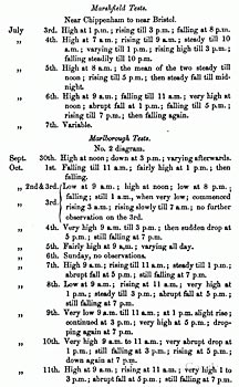
The first curve represents tests taken at Marshfield, midway between Bristol and Chippenham. Six wires, each nine miles long, extending from Marshfield towards Bristol, were looped into a continuous circuit 54 miles in length, and the insulation curve is represented by a dotted line. Between Marshfield and Chippenham six wires, each 12 miles long, were looped into a 72-mile circuit; and the result is shown by the dash and dot line on the diagrams. A wet and dry bulb thermometer at Marshfield recorded the moisture, and this appears as a full black curve in the upper portion of the engraving.
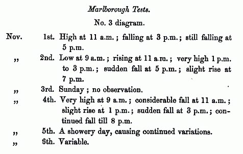
In the second and third diagrams the insulation tests of two wires, looped from Marlborough to Calne, the loop being 26 miles long, are recorded. The curve is shown by a dotted line. Wet and dry bulb readings, reduced to degrees of saturation, were taken at Marlborough in the second, and at Marlborough and Calne in the third case; and these curves appear as full black and dash and dot lines respectively. Observations were mostly taken by day, at intervals of two hours, but night observations are likewise recorded. The lines were insulated with Varley's double cup- earthenware insulators, a few shackles being interposed at heavy angles.
It may here be convenient to roughly tabulate the observed variations in insulation, for more ready consideration, leaving the actual figures recorded to be obtained from the curves.
|
|
An examination of these results shows graphically what might have been expected from theoretical considerations. Briefly it appears:
First, that there is as it were a great wave of moisture that sweeps daily over the land, having its maximum near midnight, and its minimum at noon; and that accordingly the insulation of our circuits, generally low from 7 to 9 a.m., rises to a maximum from 11 a.m. to 3 p.m., then abruptly falls, reaching a minimum between 7 p.m. and midnight.
Secondly, that very frequently the most abrupt changes in insulation take place in a most limited time; the resistance dropping from several megohms to a fraction of a megohm per mile in the course of an hour or two.
Thirdly, that the resemblance between the insulation and moisture curves is very remarkable; so much so, in fact, that it is not improbable that an extended series of insulation readings would form a more accurate register of moisture over any given extent of country than ordinary hygrometrical readings.
The almost simultaneous movements in both curves is not the least noticeable feature in the case; divergencies, when they occur, being readily accounted for by comparing the extent of line exposed to a varying atmosphere, the moisture in which was only recorded by one, or at the most two, hygrometers.
Perhaps the most useful lesson taught by these diagrams consists in the striking indication of the rapid variations which frequently takes place in the insulation of some of our best lines, in the course of a very limited period. This rapid variation in insulation, and consequently in the strength of the currents received at either end of a line, is perhaps one of the greatest obstacles to the introduction of what may be termed more refined modes of telegraphy than are at present practised. Given a certain standard of insulation that is more or less invariable, and provision can be made either in the shape of increased battery power, or increased delicacy in the receiving apparatus, to meet a given constant loss of current, but let the insulation vary within wide limits in any given period of time, and the choice of apparatus and systems of working are limited to a very considerable degree. With ordinary systems of working, very wide variations in insulation may take place without being attended with any evil results, a simple turn of a screw serving to adjust so as to meet the change; but the gradual tendency of the day is the introduction of new modes of working which demand a greater steadiness and invariability in the strength of the currents circulating through the line, and hence the desirability of concentrating attention on the whole subject of insulation.
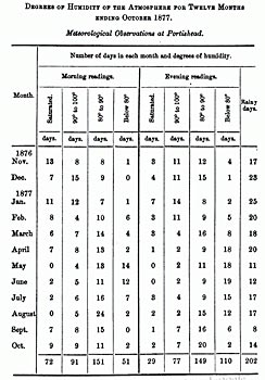
As further illustrating the variations in the insulation resistance of lines to which in this country we are subject, the following table has been compiled from the Board of Trade meteorological observations at Portishead for the year ended October 31st, 1877. It shows the degrees of moisture in the atmosphere during the morning and evening observations, and the number of days in each month when rain fell within the twenty-four hours. From this it will be seen that rain fell on 202 days out of the 365; that there were 163 days when in the morning, and 106 when in the evening the amount of moisture in suspension was over 90 per cent of saturation, a degree of humidity which, as our curves show, causes a lamentable fall in insulation. Only 51 days in the morning and 110 in the evening give less than 80 per cent, of moisture, a degree when fair insulation may be anticipated.
|
A careful consideration of this table, in conjection with the curves of moisture and insulation, will give a graphic idea of the variability of our working circuits, especially if allowance be made for the weak points in a line, such as the growth of trees, fractured insulators, and other defects which even with the best maintenance - occasionally creep in, and cause these variations to reach still wider limits.
The insulation curves justify in a remarkable degree the hour selected for the taking of morning tests in this country, as they demonstrate strongly the fact that they take the lines in their worst state, and therefore give prominence to all defects, incipient or pronounced.
Now no doubt the evils referred to above have been more or less widely felt, and attempts have from time to time been made to improve the standard of insulation, but, with few exceptions, all these attempts have been made in one groove. The original double cup has been taken as the one pattern, and it has been modified in a variety of forms. No doubt some of these present advantages over the others, either by increasing the length, or by diminishing the mean circumference, or by resisting more readily accumulations of dirt, or by providing for the cleansing action of heavy rain, but the whole of these must, from their construction, be liable to those constant resistance variations, to a greater or less extent, which have just been dwelt on; and the most that has been, or is likely to be, accomplished in this direction is the raising to some extent of the minimum insulations given in the worst weather. After extended exposure they all, however, show a lamentable falling off from the high resistance they offer when sent out from the factory.
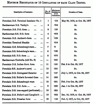
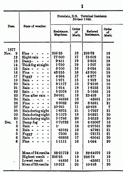
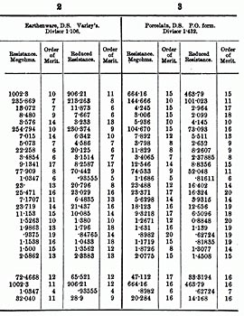
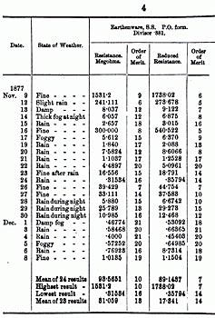
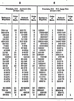
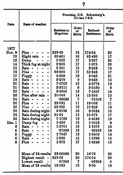
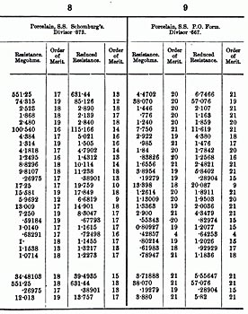
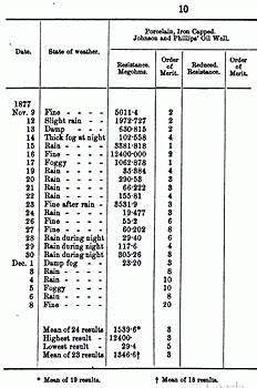
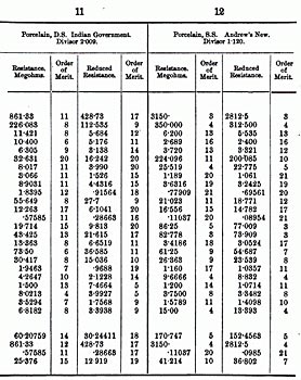
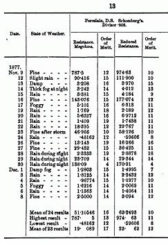
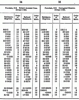
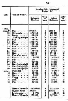
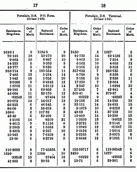
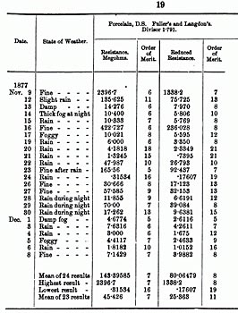
In 1876 the author, under the instructions of Mr. W. H. Preece, commenced a series of tests at Bristol on a number of different forms of insulators, the whole of which are shown on the appended table. The insulators were attached to arms in the usual manner, and fixed on a lofty pole in the store-yard of the Bristol depot. Each lot of insulators of the same description was ranged in vertical order, so as to expose all to the same influences, connected together by a line-wire, and the bolts placed in contact with an earth- wire. When tested, a well-insulated leading wire was connected to the line-wire of each set successively, and the reading recorded by a Thomson's galvanometer. These tests were continued at periods up to the end of the year 1877. Unfortunately all the insulators were not set up together, so that it would not afford a just comparison if the whole of the tests were here tabulated; but the annexed table shows the minimum resistance given by 10 insulators of each class during the tests taken in the periods mentioned opposite each.
|
It would however be manifestly unjust to take the figures opposite the insulators in the foregoing table as accurately recording the exact insulation which a line fitted with each class would reach in the course of a greater or lesser period, or to assume that these figures represent the actual relative value of each insulator. Comparative tests of various classes of insulators, on a limited scale like the present ones, are of considerable service, if accepted with due caution; but an unhesitating reliance in isolated tests of this character might readily involve serious errors. It must always be borne in mind that a fault developed in one insulator, which may be quite independent of its form, material, or general value, might at once cause the recorded results to drop materially; or in such tests as those referred to above, some accidental cause, such as a gust of wind carrying water with it from an adjacent building might saturate one set whilst leaving others comparatively unaffected. On the other hand, an accidental circumstance, such as a film of grease, even from the hand of the man setting up the insulators, and invisible on superficial inspection, might raise an insulator, for a considerable time, above its real value. Of course the tests of these insulators may be considered severe ones, for in the neighbourhood of a town like Bristol all the protected portions of an insulator, such as the inner cups, rapidly become coated with deposits of carbon, of dust, and of all the other particles that float about in the atmosphere of a manufacturing town. Even the outer portions of the insulators lose their brilliancy, and become soiled very speedily, so that the recorded insulation would naturally be lower than that given by lines running through the open country.
In the open country, however, it is only a question of time for the best insulator of the ordinary pattern to deteriorate to a very considerable extent. When newly set up, in ordinary rain the outer cup only is thoroughly wet, and the moisture on the inner cup is simply that deposited, in an extremely thin coating, from the suspended vapour in the atmosphere. As time goes by, however, deposits of all kinds accumulate, some more or less conducting, others simply acting injuriously, by increasing the thickness of moisture films. This process continues until it becomes necessary to clean the insulators throughout, when, for a short period, a high standard is again reached, but immediately deterioration again sets in, and the same process is repeated.
Now the results given in the above table show most plainly that even amongst those insulators that are supposed to take the highest rank a period arrives when the insulation occasionally becomes so low through general leakage that the working of very long lines at a high rate of speed would be seriously interfered with if not interrupted; and, inasmuch as there is a limit, which perhaps has in many instances been reached, beyond which an increase in length, size, or weight of an insulator would introduce evils which would counterbalance the advantages to be obtained from its increased resistance, it is evident that if any very marked improvement is sought for it must be in a new direction, and not in the same groove that has hitherto been so generally followed.
Perhaps the best results with the present system would be obtained by the adoption of a simple cylinder, with a very small diameter, and of the ordinary length. The idea appears to be prominent in the designing of Andrew's new form of insulator; but it is very doubtful if the system can be fairly tried with porcelain, as this substance necessitates making the diameter of the cylinder of considerable dimensions. Were it possible to obtain a material which admitted of the construction of an insulating cylinder, say one-fourth or one-third of an inch in diameter, and six or eight inches long, the wire being suspended at its extremity, probably higher results would be obtained than with even the best form of the ordinary class of insulators. Tensile strength could be given by an interior iron or steel wire, and provision could readily be made for obviating the effects of transverse strains. But for surface deterioration, ebonite would have been useful for such a purpose, and if such an idea can be ultimately applied it will probably be through the medium of one of the hydro-carbon insulators.
A new line of departure has been taken by Messrs. Johnson and Phillips, who, fully recognising the difficulty of achieving further improvements on the old lines, have boldly struck out into a new field. They have adopted as a principle the necessity for maintaining, under all circumstances, one portion of an insulator, in an unchangeable and invariable state; and as the resistance of the insulator would depend almost wholly on the resistance of this invariable section, they would thereby obtain a practically constant insulation resistance on a working wire under all circumstances. Their method of obtaining this result consists in providing a well in the interior of each insulator, and filling this well with an oil, -which having no affinity for moisture resists deposits from the atmosphere. It is so situated that direct access of water from rain-showers becomes very difficult if not impossible.
Some of the forms adopted for arriving at this result are illustrated in figs. 10, 21, and 23, (Plate 4).
Fig. 23 shows how the inventors propose applying their system to an ordinary insulator, by inverting it, and protecting the interior by means of a zinc covering.
Fig. 21 illustrates their No. 5 insulator. The lower edge, whilst in a plastic state, is turned upwards and inwards; so as to form the internal cell to be filled with the insulating oil; and another form is illustrated in fig. 10, in which an outer iron cup protects the whole from malicious injury; whilst the inner oil well is move- able up and down the bolt for filling, for inspection, &c., being held in its place by an india-rubber ring.
Mr. S. E. Phillips has supplied me with the two latter forms for experimental testing, and the results obtained are shown below.
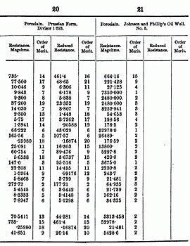
In order to afford the means of a better comparison between the various forms of insulators than was possible with the original tests, the majority of those tested in 1876-77, referred to previously, were taken down, carefully washed, and refixed; a few not considered worth retesting being omitted. To these were added a new form of terminal insulator (fig. 18), introduced in the Postal service; the new insulator with screw bolts for long important circuits, and the oil-well insulators of Messrs. Johnson and Phillips.
In all 21 forms of insulators were submitted to tests under the same conditions as those previously enumerated.
They are all illustrated in section, in figs. Nos. 1 to 21 (Plate 4), find the tests extended from November 9th to December 8th.
When considering the advantages of any description of insulator, however, it is evident that one may have a better form for insulation under all circumstances than another of an inferior shape, but it may give an equal or lesser absolute resistance, owing to the latter having a greater length, or lesser section than the former. It therefore becomes desirable to reduce the absolute results, obtained in a series of tests such as those recorded, to an unit result, so that a clear conception of the value of form may be obtained, and, if necessary, increased length or diminished section be applied to get the best results. This is done in the table in the following manner. The lengths of each cup are divided by the mean circumference, both inner and outer. The fractions thus obtained are added together giving a final fraction, the numerator of which represents the sum of the lengths, the denominator the sum of the circumferences. Now, as the resistance increases directly as the length and inversely as the circumference, if we divide by the former and multiply by the latter we get a result which would be recorded were all the insulators so made that each exposed precisely the same surface for conduction. This may be termed the form value of the insulator, and if no disturbing elements arise the figures given under this head should accurately represent the advantages and disadvantages of any given form. In the table the fractionlength by circumferenceis reduced to a decimal fraction by which each absolute measurement is divisible to obtain the unit or form value.
The results obtained are all tabulated in the same order as they appear in the illustrations in the annexed schedule, which gives the absolute resistance, the resistance reduced to unit length, and the order of merit obtained by each insulator.
|
|
|
|
|
|
|
|
|
|
|
|
|
|
Now, in considering the mass of figures given in the foregoing table, it becomes necessary to arrive in the first place at some definite basis of comparison. Evidently the highest result is not fitted for this, nor should the lowest be definitively accepted, as it might be due to some exceptional cause, independent of the general value of the insulator. The mean of the two extremes in most cases would give the same relative value as the highest, and the mean of all the observations, even, is affected very considerably by the first results, which are very unstable, for it is one of the noticeable features in these figures that not only are the original resistances never again reached, in the ordinary forms of insulators, but the nearest approach, after a few days' exposure, varies from one-fourth to one-tenth only. It appears, therefore, that the fairest results will be obtained by rejecting the first readings and taking the mean of the 23 following ones. This has been done accordingly, and although the mean of all the readings, together with the two extremes, are given in addition at the bottom of the large table, the average of the 23 readings is alone taken as the basis of comparison. The insulators are accordingly re-arranged according to their resistances in the next table for more ready consideration.
|
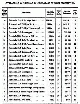
Now, at the head of the list appears No. 6, the new Post Office large insulator, and perhaps the most salient point in the whole of these tests is the extraordinary resistance recorded by it. This result does not arise from its sectional dimensions, for nothing approaching the same figures is recorded by others with a higher unit division. Such a difference cannot be due to the mere modification of form, and the author has scarcely arrived at a satisfactory conclusion as to the cause. It at first appeared as though the india-rubber ring, interposed between the bolt and the cup, took up the role of the oil in Messrs. Johnson and Phillips's insulators; it being placed out of reach of the direct action of rain, and having little affinity for the ordinary suspended moisture of the atmosphere. Further experiments, however, with other specimens have not given such high results, so that for the present the cause is somewhat obscure.
Next in order appears Messrs. Johnson's and Phillips' insulator. The tests taken at Bristol do not record such high results as those obtained by the inventors. Possibly this may be due to some defect in the oil employed in the experiments; and doubtless the inventors themselves can give a good account to the Society of what they have achieved. They undoubtedly deserve the thanks of the profession for having stepped out of the groove and designed a new method of arriving at a much desired end.
The perforated iron-capped insulator comes next in order, after the oil well form. The result doubtless arises from the protective action from the effects of dew, &c., which the iron cap exercises. It is well known that solid iron caps eventually exercise a very prejudicial effect on insulators by fostering accumulation of dust, &c.; but the perforated ones appear free from these defects for a period, though doubtless a time would arrive when they would reach the level of other insulators of a similar class without the iron hoods.
Now, with reference to the remainder of the insulators on the table, much might be said no doubt by those directly interested in their production on the advantages which each form may possess. There is, further, little doubt that some of them do not occupy their right places in the order of merit on the last table, nor do they stand so high as they might or should have done had their surfaces been chemically clean and uniformly covered with a thin layer of moisture. Such irregularities are certainly due to some extraneous causes not visible on ordinary inspection. But this fact suggests matter for serious reflection. When it is observed that, for instance, an earthenware single shed insulator takes a higher rank than a high class expensive porcelain one, which latter must under normal conditions give a far higher resistance than the former, when again it is found that of two lots of insulators of the sanio pattern, and of the same porcelain, one stands No. 8 on the list, the other No. 16, with only half the average resistance,and when further it is stated that although no extraordinary precautions were taken to insure chemically clean surfaces, for a test under practical conditions was aimed at, yet the whole of the insulators tested were handled with far more care than is possible, or is ever devoted to them in line construction,it becomes a serious question whether attention should not be turned in a different direction in endeavouring to effect future improvements. No doubt in the long run the costly large double-cup insulator, with a high unit divisor, must show its superiority over the single cup with its low divisor; but do we get the value of the extra expenditure under a system which admits of this expenditure being, to a great extent, nullified by accidental circumstances which in some cases cannot be detected on inspection? Further, after a greater or lesser period of exposure, however perfect the result recorded at first may be, a time arrives when under unfavourable climatic circumstances, rapid and delicate working becomes difficult on long wires, oven with the best of ordinary insulators. No doubt great results have been achieved with existing systems of insulation, but if the introduction of quadruplex has not quite brought us to the practical limit of improvement in the transmission of signals, with our present minimum insulation, it is probable that we are closely approaching it; and who can say, after the invention of the telephone, what other discoveries, which would revolutionise signalling, may be close at hand, but which would find us unprepared to work them, consequent on the low insulation and variability of our lines; in the same manner as the duplex system was found impracticable, when first designed, from precisely similar causes? Of course it is not urged that, in view of what some may consider problematical improvements, great and immediate expenditure should be incurred and radical changes should be introduced; but that the time is approaching, if it has not actually arrived, when another step forward should be made, and that we should be prepared to make that step. It is thought that one direction in which great improvement is possible is in the provision of an unchangeable section in an insulator, placed as far as possible beyond the reach of all accidental causes of interruption or deterioration, and independent to a great extent of climatic changes. It has already been shown how this problem may in one way be solved; doubtless other means can be designed if needed.
The CHAIRMAN: We have listened to a very carefully drawn up paper on a subject of vast importance to every telegraph engineer. [ am afraid we were not able to appreciate the value of the paper fully, because it depends so much on a number of tables which the author was unable to furnish us in a form and on a scale to exhibit to the meeting, but they will of course be published with the paper. There are many gentlemen present who would no doubt like to say a few words on the subject, who have paid special attention to the manufacture of insulators of different forms. I will call upon any volunteers from amongst the representatives of the insulators referred to this evening to favour us with remarks. Messrs. Johnson and Phillips are both here, and we shall be glad to hear them, or any other gentleman, on this subject.
Mr. S. E. PHILLIPS said: It is more than three years ago since I conceived the idea of using oil as an insulator on our land lines. The results I arrived at an early period made me feel very sanguine, and after three years' experience I am more than ever convinced that it was a step in the right direction. Mr. Gavey has described briefly the principle of my insulator: it depends upon the interposition between "line" and "earth" of a fluid insulator which will not support a film of dust or moisture upon its surface.
It is evident that the idea may be applied in a great number of ways, and we have already made a good many different forms; this, however, is a point Mr. Johnson will be able to deal with more clearly than I can.
There are one or two points I would refer to in the results given by Mr. Gavey. Curiously enough, after pointing out that nearly all insulators which have only a solid surface between "line" and ''earth," and which must in course of time give great surface leakage, he heads his list with an insulator of that character; he, however, points out that the result is somewhat a mystery to him, and I am also at a loss to understand it, except that it may in some measure be due to the india-rubber ring, which it is suggested will not condense moisture upon its surface. We, however, all know that india-rubber very soon becomes conducting on its surface, and as the test was only for the period of a month it is possible that it was merely a hygroscopic value of a clean insulator that was tested. Those of ours which we have had up over thirteen months are perfectly black and dirty, and it would be interesting to know the condition of those tested by Mr. Gavey in this respect. There is a very anomalous feature in the test of our insulator, which takes the second place in Mr. Gavey's list. The first test, which was made on a fine day, gave 664 megohms; the second, 221; on the next day, 27; and on the following day, in rain, it rose to 7,350 megohms. This is a very remarkable result, and I regret Mr. Gavey is not here, since he might be prepared to discuss the point or give some information as to the way in which the values were ascertained. The lowest he has is 21 megohmson the No. 5 [No. 21 in illustrations] insulator. It is an unfortunate thing that while our insulator was in the hands of a perfectly impartial investigator like Mr. Gavey it should have given results so much below our own. My results have, however, been confirmed by several gentlemen who have been to our works and tested the 20 No. 5. I wish Mr. Gavey had also been and seen a test taken. We however hope he may still do so. I think he has hit upon the true explanation of the difference between our results, viz., that the oil is in fault. We Rent Mr. Gavey some samples of our insulators, but unfortunately did not send the oil as wellhad we done so I am sure his results would have corresponded more nearly with my own. I had no idea that the kind of oil was so important, and I wrote Mr. Gavey some time ago to say we had used rosin oil with wonderful results, but that I thought almost any oil would do. I have myself since, with different oils, got results as low as those of Mr. Gavey. 20 No. 5 insulators, which were put up on the 5th of January, 1877, still give an absolute resistance of between 1,000 and 2,000 megohms, and on testing them yesterday morning in a fine rain, I obtained these results:"20 No. 5, absolute resistance, 1,803 megohms; 20 ordinary insulators, .1 megohm. That is to say, our 20 No. 5s' were 18,030 times better than the ordinary ones, after having been fixed in an exposed position without any attention for fourteen months.
The other form which Mr. Gavey tested is an iron-sheathed insulator. Insulators with iron heads have been mostly abandoned because of the dirt they allow to accumulate on the porcelain, but it was evident in our case it did not matter how dirty the porcelain became; therefore we may use the iron sheath with impunity. I have no doubt this form will give good results when charged with the proper kind of oil.
We have been asked a good many questions as to how long the oil will last, and whether it will answer in hot climates, but that is a question which nothing but extended trial can definitely settle. I can only say in an insulator which we have had up since January the 15th last year the oil seems as perfect as on the day it was put in, and is not, as far as can be detected, at all diminished in bulk. Anticipating this question I partly filled a glass beaker with oil on the 10th of November, 1876; I examined it carefully yesterday morning, and there was scarcely any perceptible diminution in the bulk, and its surface was perfectly clear and bright. The oil, which we hit upon by a mere accident, is clearly a very good one for the purpose. I was noticing the other day two large pans outside our laboratory one containing rosin oil and the other Stockholm tar. As the result of the men sweeping the dusty passage every morning the surface of the tar was thick with dust, whilst the pan of rosin oil retained a surface like a mirror. With reference to warm climates like that of India, I believe this oil will last a very long time without requiring renewal. We have three or four insulators fixed close to the top of an iron chimney shaft. One was charged with oil, and they have been up about six months. The heat was so intense as in one case to melt the sulphur cement, notwithstanding which I found the oil in perfect condition. [The position of the insulators and the nature of the shaft were illustrated on the black board by Mr. Johnson.] I think until the paper containing the tables referred to has been in the hands of the Members it is impossible properly to enter more fully into the discussion of this paper.
A MEMBER asked with regard to the iron-headed insulator whether Mr. Phillips ever found them bridged over with cobwebs. There was but a small space between the iron head and the cup containing the oil, and these being in close proximity to each other there was a liability of its being bridged over with cobwebs.
Mr. PHILLIPS: With reference to the close contiguity of the cup to the iron head Mr. Graves and Mr. Preece had called our attention to this, and they thought we ought to give a little more space there. I have had some of these insulators up for some months, and none of them have been bridged over in the way mentioned, and it is remarkable what a little leakage occurs from this cause; for instance, in April last I have the following note:
"20 No. 5 insulators give 30 divisions loss; examined them and found spiders' webs connecting the wire to the tree; remove spiders' webs and get 1.5 divisions; 30 divisions = 606 megohms.
"May 11th. On first testing the 20 No. 5 insulators they gave a loss of 3 divisions; on examination I found a spider's web connecting the wire to the trees; on breaking this the loss fell to .5 division, very fine rain, wind south.
"On Sept. 8th, 1877, I obtained 22 divisions loss on the 20 No. 5's. There were several webs connecting the insulators to the arms, and it was a damp and misty morning: 22 divisions = 807 megohms."
Mr. W. H. PREECE. It was not my intention to say anything on the subject of insulators. My name has been mentioned once or twice, and many of the experiments Mr. Gavey has carried out have been carried out by my instruction. Mr. Gavey himself was not able to be present to-night, but it is very probable he may be here on the next occasion. In the meantime copies of the paper will be distributed to the Members, and I have no doubt all will be able to acquire a larger knowledge of the subject than they have now, and will be prompted to ask questions, and seek for farther information than they now possess. There is no subject which occasions so much thought and trouble to telegraph engineers as that of insulation. It is their bate noir. Their first thought in the morning is how the line will work during the day; their last thought at night is how it will work on the following day. Their chief thought (whether the lines under their charge be overground underground, or submarine) is of insulation.
However, to-night we simply deal with the question of aerial insulation, connected with the earliest days of the telegraph. The first telegraph line ever laid down was that from Euston to Camden Town, where the wires were laid underground. The next was from Paddington to West Drayton, which also passed originally underground; but it was soon found that the wires did not work at all well, and they were speedily transferred from underground to a more airy position above. The first insulator ever employed was, I am told, a goose-quill. However, of course, as you may imagine, a goose-quill was not of much use for overground work, and that was replaced by a simple ringa flat disc of brown earthenware. That, too, was found to work badly, and it was replaced by the iron cone of Cooke and Wheatstone. From the cone many experiments were made by Hatcher, Physick, Little, and others, whose names, although they are living now, are almost forgotten in the telegraph world.
But one great stride in insulation was made when Mr. Edwin Clark came from his successes at the Britannia Tubular Bridge to assume the command of the engineering department of the Electric Telegraph Company, where he and his talented brother, whom we so often have the pleasure of seeing amongst us, devoted a great deal of their attention to this matter, and struck out a completely new path. Mr. Edwin Clark took his idea from the cap that covers an ordinary night-glass. We all know, who have been at sea, that night-glasses are provided with caps that extend over the object- glass, with a view of preventing radiation from the glass, and so preventing the deposition of moisture upon it.
Mr. Clark argued that if the earthenware surface of an insulator were protected with a metal cap, radiation would be checked and the deposition of moisture would cease; and experiment fully proved the truth of that idea. An insulator was made on that principle. It was of the suspended form, one of which I do not see here. It was suspended with a cap something like an umbrella, made of zinc; and it was found when these insulators were new, during the early morning and late evening, when dew falls, the inside of this metal cap was a perfectly dry zone, and insulation for a few months proved to be no longer a source of trouble. The lines worked with marvellous [sic] marvelous perfection, distance ceased to be a trouble, and the problem of insulation seemed to have been solved; but time, which destroys many of our fond notions, also destroyed the truth of this very pretty theory. It was found that dust and dirt and soot and other troubles were deposited upon the insulators, and after a short time they became as bad as ever. Then, by replacing the zinc cap by an ordinary earthenware cap, and making the insulator of another form, a great step was taken. Then Mr. Latimer Clark brought out his invert.
There is not one here of the actual form. The insulating surface being protected against the climatic effects of rain and wind, it succeeded to a certain extent in giving us again a prospect of perfect working lines; but here again the little item of time crept in, and the repetition of these dirty troubles showed that we had not arrived at perfection yet. Of course others tried to improve upon that. Amongst others Mr. Varley came to the front, and, by trying an improvement on what had been done by Mr. Clark, took another stepmerely making the insulator in the form of a double cup in two pieces. The invert of Mr. Clark took the form of a double cup. Mr. Varley conceived the idea of making the inner cup distinct and separate from the outer cup, assuming that it was almost impossible that two bad cups should be inserted together, and if one was faulty it would be remedied by the perfection of the other. This double-cup insulator of Mr. Varley is a good one. It has held its own for some years, and as an insulator in that form is nearly as good as any insulator used in other countries. Other countries also started on fresh lines, and tried various improvements. The Indian department especially, by improving upon the Prussian model, by reducing the surface and increasing the area, succeeded in producing an insulator that is in itself a very excellent one; and Mr. John Fuller, assisted by Mr. Langdon, working almost on the same model, struck in another direction, altering the form from this double cup to this conical form. Mr. Andrews had also previously started in another line, by widening the inner cup, extending it down the stem, working upon the idea that the insulation of a cylinder increases directly as its length and inversely as its breadth; and going further, Mr. Andrews departed from the cup-form, and produced this rod-like insulator which you see here. If you could make this rod infinitely thin, it would be a perfect insulator, but as you cannot have strength without thickness so it is impossible to make an insulator of this kind a perfect one.
Another step has been taken by the introduction of this corrugated surface. Mr. Latimer Clark introduced a corrugated surface in the interior of the cup, but Mr. Langdon conceived the notion of placing the corrugation on the exterior, the assumption being that where you have a surface broken into lines those fine surfaces would speedily get dry when rain ceased. The test of this form of insulator is very satisfactory.
No great step in a distinct line however was taken until Messrs. Phillips and Johnson brought out their new form, and I feel bound to confess that they have started on a thorough new basis, which has caused telegraph engineers a good deal of thought, and they have done something which certainly justifies the consideration which is now being given to the subject. At present it is a child. It has not been practically tried on a large scale. It is now being tried. The Post Office recognised at once that these gentlemen had started a fresh field, and we have done all in our power to assist them in carrying out this idea. Mr. Gavey has tested this insulator with the results shown in the paper. At present we have carried them from Westbourne Park to Uxbridge, and, in order to afford a satisfactory test, eight wires have been re-insulated with different forms of insulators. They have all been put up at the same time, and include those of Varley, Clark, Langdon, Fuller, Jobson, and Johnson and Phillips, and, should it happen that between now and the next time we meet our friend Aquarius should favour us with some wet weather, I hope we may be able to give some practical results of the testing of these various insulators. I look for great results from the latter. The tests shown by Mr. Gavey are anomalous and remarkable; anomalous because they are so variable, remarkable because the results were so far less than those obtained by the inventors, just as the tests of the Post Office form of insulator are anomalous and remarkable in the same degree as that of Messrs Phillips and Johnson. It is probably owing to the india-rubber washer inside here performing the same function as the oil in Messrs. Phillips and Johnson's insulator. My own impression is, that although this little india-rubber washer may perform its function for a month it may not do so for two months. It is a question of time, and I shall expect to find in two or three months when these insulators are tested, as in every previous case, when they get coated with dust and dirt, they will all have become similar. It is because in this pattern of Johnson and Phillips there is an unvarying section always opposing the same .surface to the current that we may hope for success. If dirt gets in we must always look for the same unfavourable results. Insulators which have been up for fifteen months have given very favourable results, and if those of Johnson and Phillips succeed in giving good results for twelve months they will certainly have done a wonderful action. Insulation is a matter of such importance that I look forward with great interest and some degree of sanguineness to the success of this invention of Johnson and Phillips. Next time I hope Mr. Gavey will be present to give the results of further experiments, and I am sure you will be interested in hearing his results, whether they are successful or not.
The CHAIRMAN: I think we must all admit that this paper cannot be fairly discussed until the tables attached to it have been in our possession, and until we have been able to master them thoroughly. We will, therefore, with your permission, adjourn the further discussion till the next meeting, and I will now only allude as briefly as possible to one or two points which I think are not touched upon in the paper. It seems to me that in constructing a telegraph line, engineers pay great attention to the strength of the insulator stalks and brackets as well as of the posts employed and to the strain on the wire, but they do not always remember the great strain which is brought upon the porcelain itself, in consequence of which imperceptible cracks take place after the line has been put up and tested. There is another thing with regard to the use of iron coverings to insulators. We have been obliged to use them in Persia, where the inhabitants are rather inclined to mischief; but I believe in climates subject to great changes from heat to cold the contraction and expansion of the metal causes the porcelain to crack, the effect of course being most damaging to the insulation of the line. These matters do not seem to have been treated of in the paper, and might perhaps be considered a little more at the next meeting. As to the form of insulator, I think we must all agree that the fewer separate parts there are the better, and in consequence the No. 5* insulator of Messrs. Johnson and Phillips seems to me preferable, generally speaking, to other shapes where screws and washers are necessary, those parts being liable to injury and likely to be mislaid or lost where they have to be carried long distances. 1 therefore think the No. 5 insulator is a most convenient form in that respect. The Indian Government have ordered some for experiment, to be used along the coast of Belochistan, between the Persian Gulf and India, a very trying country, exposed to the influences of sea-air, sandstorms, and great changes of temperature. I am inclined to believe that if these insulators answer there, they will really answer anywhere.
The discussion was then adjourned.
The following Candidates were balloted for and declared to be duly elected:
As FOREIGN MEMBER:
Mr. Bourne, Montreal.
As MEMBERS:
Captain R C. Mayne, R.M., C.B. Mr. S. F. Josephs.
Mr. H. Fanshawe. Mr. J. H. Lane.
Mr. S. H. C. Hutchinson. Mr. R B. Flindell.
Mr. A. B. Larkins. Mr. C. E. Pitman.
Major E. M. Smith, R.E. Mr. H. P. Owen.
Sir William Young, Bart. Mr. T. C. Hill.
Mr. J. W. B. Dathy. Mr. G. J. Hare.
Mr. C. Duffin. Mr. E. R. McGrath.
Mr. W. B. Melville. Mr. W. C. Darling.
Mr. A. D. Hill. Mr. E. O. Walker.
Mr. C. H. Maclean. Mr. R. W. P. Adams.
Mr. W. J. Browne. Mr. J. Ovens.
Mr. C. Nigel Jones. Mr. J. Peake.
Mr. C. B. D. Marks. Mr. Edward B. Bright.
Mr. J. M. Rutherford. Mr. T. H. Wells.
Mr. L. V. Fraser. Mr. A. J. M. Reade.
Mr. A. R. Ward.
As ASSOCIATES:
Lieut. E. P. Gallwey, R.N. Mr. C. Blackmore.
Mr. Jas. Anderson. Mr. T. W. Lapham.
Mr. H. W. Sullivan. Mr. W. Hardwick.
Mr. H. Gray. Mr. A. Smith.
Mr. H. Bull. Mr. J. Williams.
Mr. T. Hackshaw. Mr. F. Duberly.
Mr. E. R. Barker. Mr. Harold Imray.
Mr. W. L. Scott. Mr. J. H. Scott.
Mr. W. Clarke. Mr. John Henry Draper.
Mr. E. Graves. Mr. Henry Edmunds, junr.
Mr. R. Matthias.
The Meeting then adjourned.
