[Trade Journal]
Publication: Western Electrician
Chicago, IL, United States
vol. 17, no. 15, p. 179-180, col. 1-3
Electrical Utilization at Portland. Ore.,
of the Power of the Falls of the
Willamette River.
The installation shown in the cuts was made by the Portland General Electric company, of which F. P. Morey is president. The company owns the entire water power of the falls on the Willamette river at Oregon City, 12 miles above Portland, which, with a head of 40 feet, has a minimum capacity estimated at 50,000 horse power. Part of the power has already been utilized by factories and mills erected near by, and in addition to these an electric station, erected some years ago, has supplied current for lighting the streets and dwellings of Portland and for operating an electric street railway between Oregon and Milwaukee, seven miles away, the direct current and high frequency alternating systems being used.
In order to take advantage of the power of the falls the Portland General Electric company has constructed the first part of an extensive station on the west side of the Willamette river, opposite the city of Oregon. The part constructed is one-quarter only of the building, which is being put up in sections. Twenty sections will complete the building; five are already built and foundations are now being laid for the remainder. The ultimate generating capacity of the station will be 12,800 horse power.
In addition to the land covered by the station, the Portland General Electric company has purchased about 1,600 acres in the vicinity. It also controls the canal and locks on the west side of the river, constructed to allow of the passage of vessels past the falls into the navigable waters above, extending 75 miles inland.
The station building is of concrete, stone, iron and brick and when finished will have a length parallel with the river of 364 feet. The water is taken from the canal, led through an extensive hydraulic installation and discharged into the river below on the other side. The water wheel plant is from the works of the Stilwell-Bierce & Smith-Vaile company of Dayton, O., and consists at the present time of three units, each consisting of a pair of vertical cylinder gate improved Victor turbine wheels, 42 inches and 60 inches in diameter respectively. The larger wheel is an auxiliary to be brought into service only at periods of excessive high water, which the records show occur about once in every five years. The smaller wheel runs at a speed of 200 revolutions per minute and the larger at 100 revolutions per minute. Both turbines are set at the same level and each carries a pulley; that of the 60 inch wheel being fixed to the generator shaft. When the large wheel is in operation the two pulleys are belted together, the smaller wheel is disconnected and the large wheel drives the generator at a uniform speed of 200 revolutions. When the smaller turbine is operated alone the belt lies upon a shelf surrounding the pulleys.
The weight of the vertical shaft with the armature is about 33,500 pounds and to carry this a system of extra bearings is introduced, one of the ring thrust type and the other a hydraulic oil bearing, both supplementing the ring bearings on the armature shaft. They are inclosed in cases filled with oil delivered by hydraulic pressure, and are surrounded by water jackets.
The length of the generator shaft is 29 feet, and 8 3/8 inches in diameter. It is not a continuation of the shaft of the wheel but is coupled to it by means of a disk coupling, which allows of a certain free movement up and down of the generator shaft. The shaft of the 60 inch wheel runs from the coupling to a bearing set in the floor of the station. Both wheels in each section are controlled by hand wheels and both are regulated by the same governor. The belt tightener is also controlled from either floor by a hand wheel.
The water is admitted to the penstocks from the upper canal by means of a headgate operated from a platform on the canal side of the station. Each penstock is 10 feet in diameter and is constructed of riveted steel plates. Each wheel has its own flume, the water passing first through the large flume of the larger wheel to the flume of the smaller wheel, whence it passes through a tube into the tail race. In addition to this turbine equipment, an auxiliary power equipment has been furnished, consisting of a set of pumps, including a hydraulic pump for supplying oil to the thrust bearing cylinders and a duplex water pump to circulate the water in the cylinder water jackets. They are operated by two 15 inch horizontal turbines enclosed in the same flume. For the operation of the exciters, a further pair of vertical turbine wheels has been installed, each 48 inches in diameter, driving the generators by a similar system to that already described for the operation of the main machines. The complete power plant will consist of 20 three-phase generators and two direct current generators, acting as exciters. The total capacity of the station, therefore, will be 12,800 horse power, divided into 20 units, each one independent of the other.
In order to obtain the best results from the power at its disposal, the Portland General Electric company selected the three-phase system of electrical power transmission as developed by the General Electric company. One feature of the Portland installation is the employment of large blocks of power for street railway service, involving the transformation of the polyphase current sent over the line into direct current for railway circuits. The frequency is 33 cycles per second, selected on account of the large amount of power which it was necessary to convert from alternating into direct current. The current is delivered directly to the line without first passing through transformers and when it reaches Portland is transformed down to a potential of 400 volts. For the power service, the step-down transformers are connected to rotary converters which will deliver a continuous current of 500 volts for street railway service, as well as for the operation of stationary motors. Induction motors will also be used directly connected to the secondaries of the step-down transformers when this can be done to advantage.
The five sections of the building already erected are occupied in the following order: The first section contains the pumps and the accumulators for the complete station; in each of the three following sections is one three-phase alternating current generator of 450 kilowatts, or 600 horse power capacity, and the fifth section contains two 250 kilowatt continuous current generators used as exciters. Each exciter is capable of exciting all of the 20 three-phase generators, and the second has been set up as a reserve in case of accident to the first. At present, one is furnishing direct current to the street railroads in Oregon City. When the station is complete, the exciter section will be removed from the fifth section, which it occupies at present, and will be placed in the center section of the building, where the switchboards will also be erected.
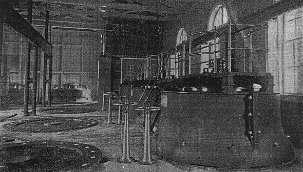
The generators are of special design and are set upon the floor of the station, the armatures revolving in a horizontal plane, with one bearing at the floor line and another on top of the armature underneath the collector rings. Each generator has 20 laminated poles. The armatures are a little over seven feet in diameter and are about two feet high. These armatures are constructed to deliver current directly to the line at a working potential of 6,000 volts effective pressure without the intermediation of step-up transformers. On account of this high voltage unusual precautions were necessary to perfect the insulation of the armature coils to avoid leakage to the ground. The armatures are wound with flat wire and each of the coils is divided into sections, each section being separately insulated. The field coils are wound for excitation of 500 volts continuous current and each has been subjected to a test of 5,000 volts alternating. The regulation in these machines has proved singularly good, the increase from no load to full load being comparitively moderate.
From the dynamos the leads are run to floor connectors and pass underneath the floor to the switchboard. The concrete floor is laid over them and thorough protection guaranteed.
The exciters are set up to allow of the armature revolving in a horizontal plane with one bearing only at the floor line. The construction of these exciters is almost identical with the General Electric multipolar type of railway generator, and each has a capacity of 250 kilowatts at 125 revolutions per minute.
| |||
| Electrical Utilization at Portland, Ore., of the Power of the Falls of the Willamette River. Interior of Station Showing Three-Phase Generators and Direct Current Exciters. |
The high tension switchboards are built of native marble and the panel method of construction is followed throughout. Each panel carries a double pole main switch for the high potential circuit and a double pole double throw switch for the exciting circuits. It also carries a rheostat for the control of the excitation of each machine and a single throw switch opening the circuit through a set of seven 32 candle power no volts. In addition the board carries a current indicator for each line and one for the exciting circuit, and a potential indicator with station transformer placed at the back. The upper part of each panel consists of a set of plug connections for coupling the machines in parallel or for direct line connections from each generator.
The exciter switchboard consists of two panels of Tennessee marble with a special switching panel between them. By means of this switching panel current for the railway service in Oregon City can be obtained from either exciter, or the two exciters can be coupled in parallel or the outgoing railroad current can be used for excitation purposes and the balance from the exciters can be used for other work.
From the generators the current passes directly to the line through the switchboard. The line is 14.3 miles long, a separate circuit being installed for each machine. It passes through an undulating country following the course of the Willamette river as closely as possible. The poles upon which the three-phase wires are strung also carry a number of wires for the 5,000 volt continuous arc current from the old transmission station, as well as the wires over which the old system of lighting with high frequency 5,000 volt alternating current is effected.
The loss in the long distance transmission line is calculated at full load at about 11 per cent.
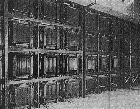
The sub-station to which the high frequency lines are brought, is a two-story building at the corner of Seventh and Alder streets, covering a space of 40 by 100 feet. The lower floor is divided into three rooms, one containing the transformers, the second the rotary converters, the other being used for a repair shop, lamp and meter room. The upper story of the building is occupied by the offices. In the transformation room at present are the necessary transformers for the three units already installed 45 transformers in all. The receiving end of each line is connected to a bank of 15 transformers per generator, five being placed between each pair of wires of the three-phase system. The transformers are mounted on an iron rack five transformers high and three wide, and foundations are already laid for six additional units. Each set of five transformers is connected to the primaries in series, and to the secondaries in parallel, although in the transformation of the three-phase current two sets only are necessary. For the large units, with high voltages, however, as employed in the present installation, it is desirable to have a large number of transformers banked. The bank, therefore, is divided into three sets instead of two, so that each group may act as a reserve to the other two sides, enabling two-thirds of the power of each generator to be delivered even it the transformers on one leg of the circuit have to be disconnected, nor is the balance of the system affected by this change of connection. The transformers regulate at a little over one per cent. variation of the secondaries from no load to full load. The transformers are of the standard General Electric sub-station type, having numerous air passages between successive bunches of iron laminae and between the coils, so that they may be cooled by artificial ventilation. This enables the transformers to be worked at a high output of efficiency and yet remain cool. The distribution of light from the secondaries is effected on the Edison four-wire system, which allows of a large territory being operated from one transformer station, and which also allows of the working of synchronous and induction motors from the lighting mains. The four-wire system is worked at 1,000 volts between wires, and by means of feeder regulators a variation of 4 per cent. in either direction is covered.
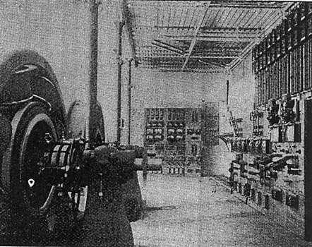
As already mentioned the direct current for the railway service is obtained by conversion from the three-phase alternating current. This is effected by means of rotary transformers, a type of machine which the General Electric company has brought to a high state of perfection. Two of these are at present installed in the sub-station and space has been left for an additional three. The capacity of each converter is 500 horse power delivered to the bus-bars of the continuous current switchboard.
The long distance transmission lines for this railway service, as in the case of the lighting circuits, are connected to step-down transformers, transforming the current from 6,000 volts on the line to 400 volts at the secondaries. The secondaries are connected to the three collector rings on one side, and the current is thus brought into the armature of the rotary converter. The alternating current at 400 volts is then converted in this machine into direct current at 500 volts at no load and 550 volts at full load delivered from the commutator side. The rotary converters are arranged for self regulation, the voltage on the direct current side compounding with the same regularity as that found in the best direct current dynamos, despite the varying losses on the long distance line and the varying armature reaction in the rotary converter. This regulation is entirely independent of the generator which receives constant excitation at all loads. The shaft of the rotary converter is extended 12 inches beyond the bearing of the alternating current side to take a small pulley from which any small machine or an arc dynamo may be driven.
It is a noteworthy fact that in spite of the long transmission line, and the increasing load on the generator, the potential supplied to the railway lines steadily rises as the load is increased.
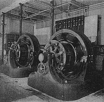
Each rotary converter has a capacity of 400 kilowatts. It is an eight-pole machine making 500 revolutions. The armature is iron-clad, carrying at one side a commutator and at the other three collector rings.
From the rotary converters the wires are taken to the power switchboards. Each converter has two panels, one for the three-phase current and one for the continuous current. The alternating current panel carries two double pole switches, one for connection to the converters and transformers and the other to connect the converter to a set of common bus-bars. An additional main switch is provided to connect the rotary transformer and the panel itself, which carries also a set of fuses, three current indicators and a potential indicator with a transformer reducing the potential from 3 1/2 to 1. The continuous current panel is of the standard direct current railway type with automatic circuit breaker, and a current indicator added for the fields of the rotary transformer. The panels may be coupled in parallel on both the alternating and continuous current side.
The lighting switchboards in the sub-station consist of one panel for each leg of the three-phase system. The secondaries from the transformers are entirely independent and the panels carry fuses and two four-pole switches for coupling the feeders directly either to the corresponding transformer unit or to the bus-bars and the switches for the operation of the feeder regulators. A current indicator is placed on each side of the four wires and three potential indicators between the four wires. On top of the switchboards are placed the main switches for opening the different feeders, and each panel is provided with ground detectors and lightning arresters.
At present the lighting rom [sic] from the three-phase system is used for large buildings, containing several hundred lights each. They are close to the city station and this distribution can be readily handled at about 400 volts. For the outlying and residential districts the high frequency apparatus with individual transformers will still be employed. Continuous current will be furnished to the rail way and to the stationary motors already installed, but new motor installations will be made with the three-phase motors, which will be run straight from the three-phase switchboard, in parallel with the rotary transformer.
The direct railway current will be carried to the East Side railway station by means of cables under the Willamette river and this distribution will reach as far as Milwaukee, where connection will be made in parallel with the 600 volt service from either station A or station B at Oregon City. The loop from Oregon City to Portland and back will thus be as follows: Beginning at Oregon City with 33 cycle three-phase current at 6,000 volts 14.3 miles will be traversed as far as Portland; the current will then be transformed to 450 volts alternating, and passing through a rotary converter, issue therefrom at 600 volts continuous, which will be transmitted eight miles to Milwaukee and connect with the continuous current from Oregon City.
| |||
| Reducing Transformers. |
| |||
| Three-Phase or Receiving Side of Rotary Converters. |
| |||
| Direct Current Side of Rotary Converters. |
 |
| Section Through the Station. |
ELECTRICAL UTILIZATION AT PORTLAND, ORE., OF THE POWER OF THE FALLS OF THE WILLAMETTE RIVER.
