[Trade Journal]
Publication: Western Electrician
Chicago, IL, United States
vol. 18, no. 21, p. 254-255, col. 3,1
Power Transmission from Lowell to
Grand Rapids, Mich.
BY J. B. W.
The value of water power, as compared with energy developed by a steam plant, is pretty generally understood and appreciated, but until recent years it has been necessary, to utilize this cheaper source of power, to locate directly upon it and to connect by mechanical means with the water wheels. The introduction of high voltage electrical apparatus has changed all this and given a commercial value to water power rights heretofore unused, and made practical and exceedingly profitable the transmission of energy long distances to an established demand for it at market rates for general distribution in either lights or motor power service.
 |
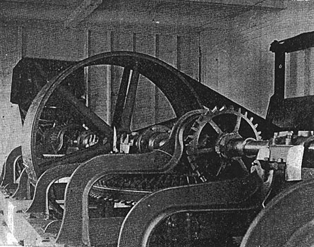
| Fig. 1. Power Transmission From Lowell to Grand Rapids, Mich. Two Views of the 200 Kilowatt Generator at Lowell. |
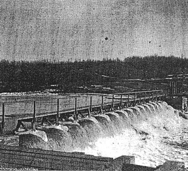
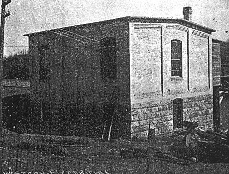
One of the longest electric transmission lines east of the Mississippi river has recently been installed at Lowell, Mich., by the Lowell Water & Light company. The power bouse is situated about one mile east of the town upon the Flat River, a tributary of the Grand. On the east side of the river is a large waste weir, which is used in time of high water. The dam is shown in Fig 2. The power house (Fig. 3), a substantial brick building, is located upon the west bank. In the basement of the building are three vertical turbines of 100 horse power capacity each (Fig. 4), two of them being Leffel and one a New America Special. These wheels furnish power for driving one 200 kilowatt "S. K. C." alternating current generator, shown in Fig. 1. The pumping machinery which supplies water for the village of Lowell is also located here. The wheels are so arranged that any one may be connected or disconnected to the main line shaft by means of clutches, thus making it possible to throw any wheel in or out without shutting down the plant. The generator is belted to this line shaft and supplies current at 1,000 volts. The town of Lowell is supplied at this voltage. Step-up transformers raise the current from 1,000 to 10,000 volts, and at this high potential supply the transmission line, upon which it is carried to Grand Rapids, 18 miles away, and there reduced by means of step-down transformers to 2,000 volts and distributed for light and power indiscriminately. Eight thousand alternations are used in this work, and the motors of the "S. K. C." type, with condensers, are used exclusively for power.
| |||
| Fig. 2. Power Transmission From Lowell to Grand Rapids, Mich. Dam in the Flat River at Lowell. |
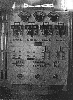
The marble switchboard (Fig. 5) in the Lowell station is perfect in its adaptation and equipped with the best apparatus obtainable for high voltage work. Two two-pole switches and two "S. K. C." circuit breakers control the Grand. Rapids lines, while the Lowell circuit is similarly controlled.
| |||
| Fig. 3. Power Transmission From Lowell to Grand Rapids, Mich. Generating Station at Lowell. |
The generator is furnished with regulator heads, by which the voltage of either phase may be raised or lowered independently of the other, thus making it possible to throw the load of the Lowell circuit upon either phase and yet maintain a perfect balance of voltage at Grand Rapids, over 18 miles away.
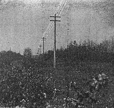
The pole line is of the most modern construction and very substantial, consisting of 30 foot poles with not less than six-inch tops, set 100 feet apart. The four No. 6 wires are carried upon two cross-arms, as shown in the woodland view in Fig. 6, and are so arranged as to make a square having 18-inch sides, the diagonal wires of which form the circuits for each phase of the generator. They are supported upon the Locke triple petticoat porcelain insulators, which give very perfect insulation, the leakage being extremely small even with a pressure of 12,000 volts upon the lines. The circuits are protected from lightning discharges by stringing a barbed iron wire over the tops of the poles, which is grounded at every other pole. For indicating grounds upon the high voltage lines static ground detectors are used.
| |||
| Fig. 4. Power Transmission From Lowell to Grand Rapids, Mich. View in the Wheel Room. |
The Stanley Electric Manufacturing company and the Lowell Water & Light company have in this installation practically demonstrated that power can be carried long distances at high voltages through a thickly settled region and distributed for an indiscriminate use for arc and incandescent lights and power with perfect success, and that by using these high voltages the losses in the lines can within a commercial basis be reduced to less than the average losses in the distributing circuits of low tension direct current central stations in large cities.
| |||
| Fig. 5. Power Transmission From Lowell to Grand Rapids, Mich. Switchboard in Station at Lowell. |
The officers of the company are: President, O. C. McDonald; secretary and treasurer, Charles A. Church; superintendent, L. W. Kutsch. The pole line was constructed under the supervision of M. M. Wood of Chicago, and the installation of the electrical equipment was made by W. B. Jackson, one of the engineers of the Stanley Electric Manufacturing company.
| |||
| Fig. 6. Power Transmission From Lowell to Grand Rapids, Mich. A Glimpse of the Cross-Country Line. |