[Trade Journal]
Publication: Western Electrician
Chicago, IL, United States
vol. 21, no. 16, p. 220-221, col. 1-3.1-2
Wagner Alternating Apparatus.
For years the Wagner Electric Manufacturing company of St. Louis has been identified in the closest manner with the development of electrical apparatus. Starting in a conservative way, this concern has kept continually increasing its plant until it now occupies one of the finest factories in the United States for the production of its varied product. As the alternating apparatus branch of this company's business, however, is the one through which it is best known, the accompanying cuts are of interest in that they present a good idea of the variety of types of the company's product.
 |
| Fig. 1 Wagner Alternating Apparatus. |
With reference to self-starting single-phase alternating current power motors, the Wagner company states that pressure is being constantly brought to bear on owners of stations to induce them to throw away their single-phase apparatus and install instead polyphase apparatus. The assertion is made that no alternating current central station can be made to pay until a day load is secured, and that with single-phase apparatus, such a day load cannot possibly be secured, for the very simple.reason that "there are no commercially successful single-phase alternating current power motors." Such an assertion, the Wagner company claims, is now a flat contradiction of fact, for it has had in operation for many months, undergoing the most severe tests to which power motors are ever subjected, single-phase, self-starting induction motors. The principle of the motor is extremely simple, there being a primary and a secondary element, bearing the same relation to each other as the primary and secondary coils of a static transformer. The primary constitutes the stationary element corresponding to the field of a direct current motor. The secondary is the movable element, corresponding to the direct current "armature." This secondary is constructed to operate in a double way. For starting, it is thrown in series with the primary by means of carbon brushes running on a commutator. With this connection the operation of the motor is in every essential feature exactly that of a series direct current motor. On attaining the running speed the connections are simply changed, the commutator, in the operation of changing, being completely short-circuited and the carbon brushes lifted off. The motor then runs as a non-synchronous induction motor. These motors are not affected by switching at the station, nor is their operation interfered with by the interrupted electromotive force on the line. As they are induction motors, they do not run in synchronism with the generator at the station and do not experience the unfavorable condition of what is known as getting out of step with the generator.
| |||
| Fig. 4 Wagner Alternating Apparatus. |
They further will not slow down and stop when a heavier load than normal is applied, as is the case with the synchronous motor, but when the excess load is discontinued will pull up to normal and continue the same as before. An illustration of the motor is presented herewith. Fig. 1 shows the general mechanical design. The very rapid rise of the efficiency curve on light loads is a significant feature. Not less noticeable and noteworthy is the high efficiency maintained up to the point of 50 per cent. overload. This small drop in speed with increased loads is a further point of superiority, while the high power factor at all loads is a characteristic unprecedented in motors of this capacity. It is possible to pull up from rest double the rated load of the motor with a current only exceeding the load current by 50 per cent. The motor very quickly runs up to the load-service speed, and operates under any and all loads with smoothness and quietness. Another feature which will prove most attractive to the central station man is that there are no pulsations of current with this motor. The motor is also absolutely unaffected by, momentary interruptions in the current supply or a sudden change in frequency or voltage, resulting from necessary station switching.
 |
| Fig. 2 Wagner Alternating Apparatus. |
The frequencies generally found in single-phase stations are 16,000 and 7,206 alternations per minute. This design of motor is guaranteed to operate with equal effectiveness on either.
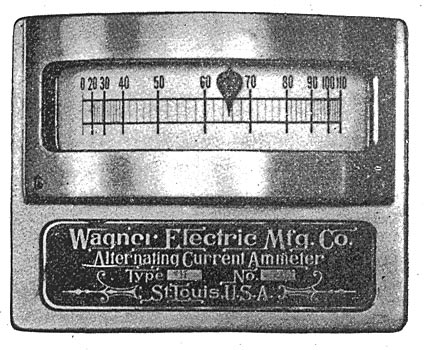
One of the needs in alternating current central station equipment has been a reliable dead-beat, wide-scale, indicating switchboard instrument. This company has developed a line of indicating voltmeters, ammeters and wattmeters which it claims meet every requirement. These instruments are a radical departure in design, both mechanically and electrically. The moving parts are carried on a vertical shaft, the lower point of which runs in a jewel bearing. This point is at all times immersed in oil, and, accordingly, friction is reduced to a minimum. The deflecting force is so very great that every point on the scale has a positive differential value, and successive deflections, with the same deflecting force, are absolutely the same. Furthermore, the inductive error is eliminated, voltmeters, for example, reading practically the same on direct curent as on alternating current of 16,000 alternations. Finally, every scale is accurately plotted by independent calibration, and as there are no parts the constant of which is subject to change, indications are permanently reliable.
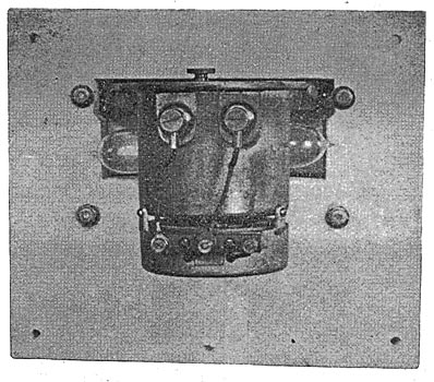
In the Wagner instruments. Figs. 2, 3 and 4; the oscillating of the indicating needles has been wholly eliminated by floating all the moving parts in a light, colorless, odorless oil, a couple of small aluminum vanes serving to afford a dashpot action by which needles are held stationary against any passing, instantaneous disturbance, and at once brought to rest on throwing over. That the instruments are economical in operation is apparent from the statement that the voltmeter consumes but seven watts on 110 volts pressure.
 |
| Fig. 5 Wagner Alternating Apparatus. |
Admirable provision has been made for illumination of the scales; the lamps, two in number for each instrument, are eight candle power, 50 volts each, connected two in series and mounted on a special bracket which holds them in the necessary position. The body of the instrument, which extends through the board, is highly japanned in black. The front cover is of polished brass. Provision is made to keep all dust out of the instrument. The oil is carried in the cup forming the rear portion of the body. The cover to this portion is removable, affording easy inspection and filling of cup with oil. The ammeter is identical in general appearance with the wattmeter and voltmeter, but the principle employed is somewhat different. In instruments up to 100 amperes capacity the entire current of the circuit is sent through the instrument coil. Above 100 amperes use is made of a series transformer, the primary of which is cut in oh the bus-bar. In the voltmeter movement use is made of the dynamometer principle. The scale, being one of 67 degrees arc, is almost absolutely uniform throughout the range. Scales can be plotted to any value desired, from zero to the maximum called for, or from any specific point to the maximum. The maximum pressure of operation is 150 volts. Above that point step-down transformers are furnished.
| |||
| Fig. 3 Wagner Alternating Apparatus. |
In the wattmeter the dynamometer principle is again employed. The pressure coil is connected to the 100 volt ends of a step-down transformer. The series coil, for circuits of 25 amperes, takes the entire line current. Above that amount a series transformer identical with that used for ammeters is employed.
Figs. 5, 6, 7 and 8 show respectively the Wagner 500 light indoor type transformer, the 100 light type D transformer with bracket fuse boxes, the Wagner XL fuse cut-out box and a glimpse of a line of the company's step-up transformers, 600 kilowatts, 10,000 volts, water jacketed.
 |
| Fig. 6 Wagner Alternating Apparatus. |
The Wagner transformer is the result and embodiment of several years' experience in the use of transformers in one of the largest existing stations. High and practically indestructible insulation, though costly, is obtainable, and such material, the company states, is used throughout in its transformers. It has been the company's purpose further to effectually guard against heat effects and electrical strains. To such a high degree of perfection has this been carried, that every transformer readily withstands 10 times the normal primary voltage, impressed between the primary and secondary coils. Standard transformers are tested with a pressure of 10,000 volts alternating current between primary and secondary and between primary and the iron core. An insulation test is made between the secondary and the iron case and the iron core of 6,000 volts. The company is therefore ready to guarantee transformers against burning out from any cause, except overload, fire or mechanical injury, for a period of two years from date of purchase. Leakage or magnetizing current constitutes the principal loss or waste in the transformer, and therefore demands the most careful consideration. On account of hysteresis, this leakage current is dependent to a large extent on the quality of the iron employed, and may therefore differ considerably in two transformers in all other respects identical in design. The iron used in Wagner transformers is made by one manufacturer expressly for them. Owing to this careful selection of iron and to an ingenious device in the design, transformers are produced differing from one another in characteristics and efficiency by an incredibly small amount. The Wagner company believes it has discovered the causes of the ageing of. transformer iron, and has succeeded in determining a formula for the preparation of the iron by which the causes of this change are eliminated. Step-up transformers are now being introduced to a large extent for long-distance transmission. These step-up transformers, being used in large units, are very efficient, and render such service very satisfactory. The company makes these in standard sizes from 100 lights to 3,000 lights capacity for 4,000, 5,000 or 10,000 volts.
 |
| Fig. 7 Wagner Alternating Apparatus. |
The XL fuse cut-out box is a comparatively new form. It is adaptable for use on primary circuits of transformers as a protective device against short-circuiting or overloading, or for primary distributing circuits as a protective or switching device. It is waterproof, affording perfectly safe replacing of fuses on live circuits, and assures reliable blowing of fuses. On opening the box, the lid comes forward and down, the top porcelain block containing the fuse drawing out with it. In this way the opening of the box breaks the circuit. The porcelain block containing the fuse is still further removable by simply drawing out from the end of the lid, thus entirely detaching it from the box. The resistance to this removal is a spring between the block and the lid, so constructed as to prevent the block sliding out by its own weight.
The porcelain parts fit closely together, the spring in the lid serving also to press the upper half down on the lower half. A rubber gasket completes the perfection of the joint.
 |
| Fig. 8 Wagner Alternating Apparatus. |
