[Trade Journal]
Publication: Western Electrician
Chicago, IL, United States
vol. 23, no. 8, p. 99-100, col. 1-3
Snoqualmie Falls Transmission.
In the middle of March the Snoqualmie Falls Power company began the work of building a plant at Snoqualmie Falls to utilize and transmit the power of the cataract to the cities of Seattle and Tacoma, Wash. At that time the Western Electrician gave a brief preliminary account of the project and a picture of the falls. Now the work is well under way, several important contracts have been let, and this journal is enabled to give further details, with pictures showing the work accomplished, of a plant which will embody several features of exceptional interest.
Snoqualmie Falls is an unbroken cataract of 268 feet in the Snoqualmie River, 22 miles east of Seattle, in an air line. Its importance as a possible source of power for use in the adjacent cities has long been realized, and the project of utilizing the power is not a new one. It was not until this year, however, that the necessary financial arrangements were finally completed and the work of building a plant actually begun.
The Snoqualmie River is formed by the union of three widely divergent forks which drain a large section of the western slope of the Cascade Mountains. The water-shed is said to be about 460 square miles in area, and the rainfall is placed at 85 inches a year. During the heat of summer the melted snow from the mountain summits keeps up the supply of water. At the lowest stages of the water the power of the falls is placed by conservative calculation at from 20,000 to 30,000 horse power. The plant now going in will have capacity to deliver 6,000 horse power of this in the cities named, after deducting all losses. Provision is also made for extension.
| |||
| Snoqualmie Falls Transmission. |
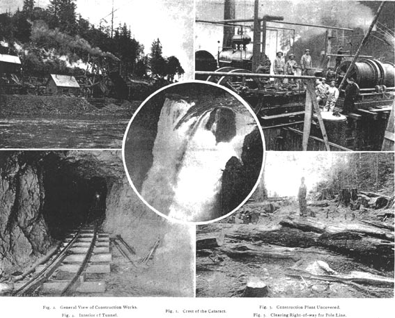
The cataract is a very picturesque and impressive one, and it is situated in a sparsely settled and thickly wooded country. The central view in the group of pictures on this page (Fig. 1) shows the crest and upper portion of the falls, and Figs. 6 and 7 on page 100 show the character of the country thereabouts.
Briefly stated, the plan comprises an intake in the channel of the river about 300 feet above the falls; a shaft 250 feet thereunder, with a steel pipe to contain the column of water; a large excavation at the foot of the shaft, containing a receiver for the water, water-wheels, generators, transformers and switchboard; a tunnel or tail-race, through which the water flows from the water-wheels to a portal at the lower level of the river, and an electric transmission line from the subterranean power house to the distant points of consumption.
Mr. Charles H. Baker of Seattle, who is the president of the company and its chief promoter, was in Chicago last week to place contracts for the electrical equipment of the plant and to transact other business connected with the work. He states that the shaft is nearly down to the required depth; that the rock excavation for the power-house chamber is within two months of completion and that the tunnel is finished. The shaft is 250 feet deep and eight by 25 feet in horizontal section; the chamber at the base of the shaft will be 200 feet long, 50 feet wide and 25 feet high, while the tunnel leading from it is 660 feet long 15 feet high and 15 feet wide. The rock is hard and free from fissures. The excavation is done by compressed-air drills.
A general.view of the construction works is shown in Fig. 2, while Fig. 3 gives a nearer view of the air-compressing and hoisting machinery, Fig. 4 shows the interior of the tunnel and the tramway used for the dump-cars. More comprehensive views of the tunnel works below the falls are shown in Figs. 6 and 8. The former also gives a view of the long stairway leading from the upper works to the tunnel portal, while the latter shows a compressed-air pipe and a conveying cable.
The construction plant is supplied with steam by two tubular boilers of 125 horse power each. A double-friction drum and brake-hoisting engine of 75 horse power, with reversible link motion, raises 6,500 pounds from the shaft at the rate of 450 feet per minute on one drum, each drum working separately. The rock is raised on an improved safety platform cage, suspended by wire rope, of which there is 600 feet on each drum. The engine raises the rock taken from the shaft to a tower which has been erected directly over the mouth. From this tower the rock is carried by a gravity tramway to a crusher, which in 10 hours will crush 70 cubic yards to a size of 1 1/2 inches, being operated by a 15 horse power engine. The rock is piled up for use in building the dam and intake, which will be the last step preliminary to installing the generating machinery.
The mining is done by 10 compressed-air drills, the power for which is furnished by an Ingersoll-Sergeant compressor. It draws in 960 cubic feet of air a minute and produces an air pressure of 100 pounds per square inch. The compressed air passes into an iron receiving tank, 4 1/2 feet in diameter by 12 feet high, whence it is distributed through iron pipes down the shaft and into the tunnel.
When the excavation is completed the intake (a channel 20 feet wide and 60 feet long) will be built and a dam will be built diagonally across the stream along a ledge of rock which extends across the river at the lower edge of a pool 300 feet above the falls. This dam will maintain the water at a constant depth. It will be 450 feet long, 15 feet high, 15 feet wide at the base and eight feet wide at the top, and will be of solid concrete. Near its center will be a bear-trap dam which will be dropped to allow the escape of flood water. Five thousand barrels of Milwaukee cement have been ordered for the hydraulic work. It is said to be the plan to divert the course of the whole river through the shaft and tunnel while the dam is being built, the falls running dry. When the dam is finished the water will be again cut off from the shaft and tunnel and will return to its accustomed channel; the pipe will be set in the shaft, the elevator by which the men are to descend into the subterranean chamber will be put in place, the dynamos and water-wheels will be installed, and the wires stretched which are to carry the current to the surface.
The receiver at the bottom of the water column will be tapped for four water-wheels, and each water-wheel will drive a 1,500-kilowatt three-phase alternating-current generator. These machines will be operated at 7,200 alternations per minute, and the output will have an electromotive force of 1,000 volts. The pressure will be raised by static transformers in the subterranean power chamber to 25,000 or 28,000 volts, which will be the initial line voltage. Two 125-volt exciters of 75 kilowatts each will complete the machinery equipment. All the generators, transformers, exciters, switchboard apparatus, etc., will be supplied by the Westinghouse Electric and Manufacturing company.
| |||
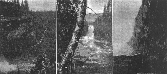
| Snoqualmie Falls Transmission. Fig. 6. Foot of Falls and Stairway. Fig. 7. River Below the Falls. Fig. 8. Whirlpool, Tunnel Entrance, Air Pipe and Conveying Cable. |
Aside from the exceptionally high voltage to be employed, the transmission line will be of great interest, from the fact that aluminum conductors will be used, and the plant will thus be the first in the world to use aluminum to transmit electricity to a considerable distance in commercial practice. Mr. Baker has entered into contract with the Pittsburg Reduction Works for about 500 miles of aluminum wire of No. 2 and No. 3 B. & S. gauge. This wire is pure aluminum, with the exception of about l 1/2 per cent. of copper. While it has only about 60, per cent. of the conductivity of copper, yet the difference in weight is so great that, for a long transmission line of this character, Mr. Johnston, the chief engineer of the Snoqualmie Falls Power company, calculates that the use of the lighter metal is advantageous both from a financial and an engineering point of view. It is possible that, with the prevailing high price of copper, the Snoqualmie installation, if it is as successful as it is hoped, may prove to be a pioneer in an extensive use of aluminum for electrical transmission purposes.
Four circuits of three wires each will take the current from the falls to Seattle and Tacoma. Two circuits supply each city, and there are two distinct pole lines. These pole lines, composed of cedar poles cut in the vicinity and the aluminum wire, run side by side from the falls for 19 miles to Renton, where they diverge, one going to Seattle and the other to Tacoma. The length of the pole line from the falls to Seattle is about 30 miles, and to Tacoma about 44 miles. The pole lines follow, as nearly as possible, a direct line to Renton. They are on country roads wherever possible, and for a long distance run due west along section lines. In such cases a private right-of-way has been acquired, either by free gift or at a small expense. From Renton the Seattle line will follow the county road over Beacon hill to the city. and the Tacoma line will run almost due south through Auburn and Kent.
For long distances the right-of-way runs through unbroken forests of fir. A strip 25 feet wide is cleared of all vegetation, and every tree within 300 feet of each side, which could possibly strike the wires, will also be cut down, so that all danger from forest fires or windfalls will be avoided. Some of these giant firs are 300 feet high and six or eight feet in diameter. The wind has an immense leverage on.these great trunks, and if one should be blown across the line it would, of course, be a serious interruption to the service. A photograph showing the clearing for the right-of-way near the falls is reproduced in Fig. 5. A pretty view showing the river below the falls and the character of the country is given in Fig. 7. The poles are from 36 to 60 feet high, according to the nature of the ground. The insulators are of the Redlands type, made by C. S. Knowles of Boston. They are of porcelain, triple-petticoated and of unusual size.
While each circuit will ordinarily carry about one-half of the power destined for the city to which it runs, it will be possible, in case of breakdowns, to carry the entire current on one circuit with an increased drop. A further precaution will be the establishment at Renton of a switching station, by which, in case of breakdown oh the Seattle circuits, the current from one of the Tacoma circuits can be conducted to that city and vice versa. By linking the two lines together it will be possible to obtain an electrical circuit 150 miles long for testing. With such a circuit, aluminum conductors and 28,000 volts potential some highly important and interesting data should be secured.
At the points of consumption the potential will be reduced in sub-stations and the power will be sold to street-car companies, electric-lighting plants, flour mills, machine shops and other industries. Much of it is already under contract. Coal is not cheap in Tacoma or Seattle, and Mr. Baker declares that the company will be able to furnish power cheaper than it can be produced by any fuel and that manufacturers will take out their steam plants and install electric power.
The work is proceeding under the technical direction of Thomas T. Johnston, chief engineer, and James J. Reynolds is the superintendent of construction. Both are Chicago men, and it is Chicago capital that is building the plant. The cost of the work is estimated at $500,000, and the company is capitalized for that amount. It is hoped that power will be delivered early next year.
