[Trade Journal]
Publication: Western Electrician
Chicago, IL, United States
vol. 23, no. 25, p. 338-339, col. 3,1-3
High-voltage Power Transmission.
BY CHAS. F. SCOTT.
PART IV.
POWER-TRANSMISSION PLANTS IN OPERATION.
Beginning with the plant at San Bernardino and Pomona, which began operation in 1892, using 10,000 volts and transmitting 30 miles, a constantly increasing number of plants have been installed operating at 10,000 or 15,000 volts. In some cases there has been little or no trouble experienced with the transmission lines, while in other cases the experiences have been less satisfactory. The principal trouble seems to have been a poor grade or an insufficient size of porcelain insulator. In other cases the insulators, sometimes porcelain and some-times glass, have given almost perfect satisfaction.
The superintendent of a power company which has been running 15 months with about 15,000 volts, reports that they "have had absolutely no trouble whatever of an electrical nature." Some insulators were broken because they had been used as targets by small boys or hunters, but only the outer petticoats were broken, and no short-circuits occurred, although in some cases insulators were in use for months with most of the outer petticoats chipped off. The distance of transmission is 12 miles. Porcelain insulators are used.
In another plant, which has been in operation about a year and a half, employing 15,000 volts for a distance of nearly 30 miles, there have been but three shut-downs on account of line difficulties. These were due to the breaking of insulators at a point where the line was spiraled. In one case the repair was made in half an hour, and in the other case a few minutes interruption to the service was sufficient for repairs.
The line is regularly patroled, and if a defective insulator or pin is found, the generating station is notified by telephone and the line is shut down for a few moments at noon. In one case two poles were burned by a defect in the insulators on the top of each. The poles burned to the ground, leaving the line hanging clear, without anyone at either the generating station or sub-station being aware of the fact.
Troubles have arisen on some lines by the burning off of pins by the passage of sparks from the outer edge of the insulator to the pin. These sparks make small holes in the pin no larger than a needle point, but after continuous sparking for some time the pin becomes entirely charred. An iron pin suggested itself as a remedy, but additional strains and liability to breakdown are liable when a conductor is placed within the insulator. The burning off of pins has occurred where small porcelain insulators are porous and the outside glaze is imperfect, while the glaze on the inside is good. When the porcelain is filled with water the current readily passes through it to the lower rim of the insulator and then sparks across to the pin. In one place which has been running for about three years some 250 pins burned off. The early insulators have been replaced by larger and better ones and this defect has disappeared.
A 10,000-volt line which runs for a dozen miles or more within a few hundred yards of the Pacific coast has burned cross-arms on nearly every pole. The cross-arms near the ends of the line which are away from the coast, are not burned. Usually the burning appears as a mere blackening of the cross-arm for a short space between the insulators, on one side of the arm. In some cases the charring is deeper, and appears on both sides. The side on which almost all of the burning occurs is the one toward which the winds come from the ocean, bearing the mist of salt water. The wire shows discoloration, and the iron braces for holding the cross-arms are in a few cases eaten through. Moreover, the cross-arms were green and full of sap when erected. The early porcelain insulators were porous, and have now been replaced, and the pins are of iron. The charring has ceased almost entirely since the new porcelains were put up.
It may be observed that in the plants which are herein referred to and in the experimental tests no mention has been made of insulators with cups containing oil for reducing the surface leakage. Insulators of this kind were used in the Frankfort-Lauffen experimental transmission line at 30,000 volts. Practically, however, the surface insulation is adequate without oil cups, and the principal duty of the insulator is to prevent the current passing over the surface and jumping to the pin or cross-arm, a matter with which the oil would have nothing to do.
Telephone lines are in use in a number of plants, placed on the poles which carry the transmission wires. The telephone lines are usually placed some distance below the transmission wires and are crossed at frequent intervals. The telephones in general work very satisfactorily.
There appears to be practically nothing in power transmission in Europe using high potentials outside of Switzerland. The installation in Paderno in Switzerland is operating at 15.000 volts, the highest voltage which has been used in that country. The damp weather is one oi the limiting factors. The insulators used are porcelain with a triple petticoat.
40,000 VOLTS IN COMMERCIAL SERVICE.
The highest voltage which is used for transmission is in the Provo plant of the Telluride Power Transmission company in Utah, which transmits power 35 miles to the Mercur mills at 40,000 volts. Raising transformers are three in number and are connected in the star iorm. Each transformer has a capacity of 250 kilowatts. The middle points of both the high-tension and low-tension circuits are grounded. In general design these transformers resemble the transformers used in the high-tension tests at Telluride, the design and construction having been under the direction of the same man in both cases. The line extends from Provo, at an elevation of 4,500 feet, to Mercur, at 2,000 feet above Provo, and the line reaches an extreme height of about 10,000 feet above the sea level. Three miles of the line are strictly mountain construction. The lightning protection is afforded by choke-coils and Wurts non-arcing metal arresters. The insulators are of glass. The design was based on the tests at Telluride, and they were made especially for this plant. The form is shown in Fig. 16. The insulators are held on special pins of oak which are thoroughly paraffined. The lower part of the insulator is five inches above the cross-arm.
| |||
| Fig. 16. High-Voltage Power Transmission Insulator Used at Provo for 40,000 Volts. |
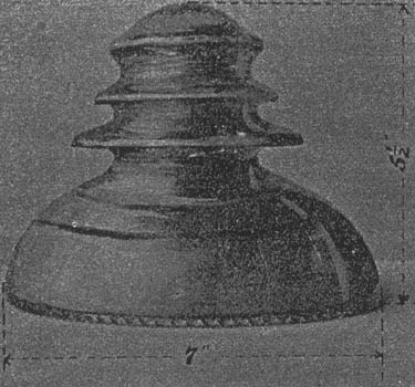
In dry weather there has been no difficulty whatever in operating. The insulators do their work as effectively as could be expected if the voltage were only a few thousand volts. When everything is dry, the line will operate without difficulty, even if some of the insulators are off and the wire rests upon the cross-arm. When it rains there is sometimes trouble. It is indicated in the station by the ammeters giving quick swings, showing momentarily strong currents. Sometimes this is apparently a short-circuit and blows a fuse. In every case when there has been trouble on the line it has been in rainy weather, and broken insulators have been found which located the trouble. It is certain that in most cases these have been previously broken by bullets, and in other cases it is probable that the insulators were likewise broken. It is believed, therefore, that had there been no intentional breakage of insulators there would have been no trouble upon the line since the plant began operating in February last. A few of the insulators near the station are not far from the overflow and are in a moisture equivalent to a rain all the time without doing any damage. Snow has often backed from the cross-arm up against the bottom of the insulator and around the first petticoat. It is usually found that the part of the insulator around and near the wire does not receive deposits of moisture or frost, but remains dry, the particles being repelled. At this plant, current for about 700 horse power is carried through three fuses of copper wire 0.01 inch in diameter. Iron wire is used on a branch line for transmitting about 100 horse power for about three miles.
| |||
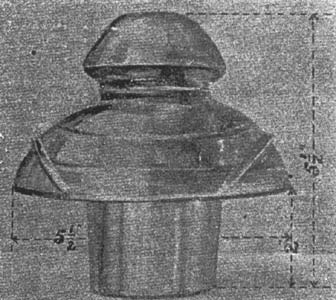
| Fig. 17. High-Voltage Power Transmission Insulator Used by Colorado Electric Power Company for 20,000 Volts. |
This plant has been in operation in winter and in summer, "in thunder, lightning or in rain," the sole supply of power for the enormous De Lamar mines and mills at Mercur, and is a happy and fitting consummation of the high-tension tests described in the beginning of this paper.
LIMITATIONS OF HIGH-VOLTAGE TRANSMISSION.
The important commercial question is: To what distance can power be transmitted? The relation between distance and voltage is well known. The same weight of copper can transmit with equal efficiency the same power to any distance, provided the voltage, is increased directly as the distance is increased. The limiting commercial ratio between voltage and distance is easily found. If the distance be three miles per 1,000 volts and the loss 16 per cent., the cost of copper is about $20 per horse power. The interest on the latter investment is about $1 per year. A distance in miles equal to three times the number of thousand volts may therefore be covered without an excessive annual charge per horse power for copper. The limits to the voltage which are practicable depend principally upon the insulator and upon the loss between wires.
The Insulator. The two fundamental requirements are dielectric strength sufficient to prevent puncture and a size and form which will prevent the passage of the current around the insulator. A given insulator will be adequate for a higher voltage where the atmosphere is comparatively pure and dry than it will be under other conditions. The rapid progress which has been made in the design and construction of insulators during the last few years will doubtless provide an insulator which will accommodate the highest voltages that can be used due to other limitations. The insulator, therefore, while remaining the critical point in a transmission system, will probably not determine the limit of practicable voltages.
Loss between Wires. The loss between bare wires at high voltages seems to determine a positive limit, beyond which the voltage cannot be increased. This loss is subject to variation due to diameter of wire, distance between wires and wave form of the electromotive force, but the variations which may occur under favorable commercial conditions locate the point, of increase of loss about 50,000 or 60,000 volts. Under favorable conditions this may be raised somewhat, but it is not probable that any material increase can be made.
Amount of Power. The amount of power to be transmitted involves some interesting commercial limits. There are certain elements in a transmission which do not vary greatly with the amount of power transmitted. Thus, the charging current to the line will be practically the same whether the wire will transmit 1,000 horse power or 100 horse power. If the charging current happens to represent 300 horse power it would be insignificant in one case, but for the smaller output it would require generating apparatus several times that necessary for the actual power.
It is not mechanically practicable to use wires as small as would be sufficient, in so far as conductivity is concerned, for transmitting a small power. For example, a No. 7 copper wire, which is as small as is ordinarily used, if employed in a three-phase circuit 50, miles in length, will transmit over 1,000 kilowatts at 40,000 volts with 10 per cent. loss. If only a few hundred kilowatts were to be transmitted, the cost per kilowatt would be excessively high, and, on the other hand, a lower voltage could be used without undue loss. In some cases, indeed, where a high voltage is used for small power, as, for example, on a branch circuit, an iron telegraph wire would have ample conductivity. In other cases an aluminum wire could be used to advantage, as an aluminum wire of the same conductivity as a copper wire has only about half the weight, and possesses greater mechanical strength in comparison to its weight.
It may also be noted that high-voltage transformers cannot be economically built for small output, as the insulation spaces required are so large. The cross-section of the copper is often not more than 10 or 20 per cent. of the area of the opening in the iron. The cost per kilowatt increases very rapidly when the size of transformer falls under a few hundred kilowatts.
Cables and Conduits. The overhead transmission line has been considered, and its limitations are the insulating strength of the insulator and the losses through the intervening medium. In a cable or a conduit the insulation must be provided continuously, instead of at points a hundred feet apart. Rubber-covered cables are made for 10,000 and 20,000 volts, but it is quite possible that it will not be commercially practicable to make cables for much higher voltages. The effect of continued electric stresses on the insulation of the cable, which is an unknown factor, may prove to be a very important one. A conduit composed of a pipe containing oil, in which the wires are separated by glass tubes, has been proposed. Many mechanical difficulties arise in constructions of this kind; the cost is high, and the action of continued high voltages on solids and liquids opens a field which is little known. A suitable insulation on the wires on high-voltage lines may enable higher voltages to be used than can be used with a bare wire.
Liquid air, with its high insulating properties, and the low temperature and consequent high conductivity which it would give to a conducting wire, may enable us to use air insulation in a new way.
Difficulties and Precautions. High voltages have been referred to in this paper with perhaps undue familiarity. Familiarity with high voltages is not one which breeds contempt, A voltage which can produce sparks several inches in length, which can be felt through several feet of air, which causes hissing sounds, which produces luminosity, and which in a confined room generates strong odors of ozone, is one which creates profound respect. Dangers and difficulties accompany it, and the highest intelligence, vigilance and excellence must be employed to avoid accident and insure success. While ordinary types of construction do not seem to reach their limitations until some 50,000 volts is reached, and pressures of this order have been and are in regular use, nevertheless they are not to be used indiscriminately or where they can be avoided. There are difficulties enough in handling 15,000 and 20,000 volts. As the pressure is raised the liabilities to trouble increase at an alarming rate. It is, however, a fact that these voltages have been and can be used, and also that no new or modified methods of transmission will be required before 50,000 or 60,000 volts can be employed for distances tip to 150 or 200 miles
APPENDIX A.
INSTRUMENTS AND METHODS USED IN TELLURIDE
MEASUREMENTS.
The Wattmeters. At first all the measurements of power were made inthe low-tension circuit. The attempts, to measure the power delivered to the line by taking the difference in the readings of the wattmeter in the low-tension circuit of the transformers when the lines were on and when they were oft proved worse than useless. This was due to the fact that throwing on the lines distorted the electromotive force wave impressed on the transformer. As a result, at low voltages, readings obtained in this way indicated a negative line loss, and it was only when the voltage was raised to such a point that the line loss was greater than the reduction in iron loss, due to the electromotive force distortion, that positive results could be obtained; such results were of course incorrect. In order to overcome this, it was determined to balance on the wattmeter the effects of the iron loss in one of the power transformers against that of the other in such a manner that both transformers would be subject to the same electromotive force distortion, and the iron loss would therefore at no time register anything on the wattmeter. The line loss could then be measured directly. This was accomplished, as is shown in Fig. 18.
 |
| Fig. 18. High-Voltage Power Transmission. Overcoming Distortion. |
Here the transformer which supplies the line is designated as the "power transformer," while that which is used in balancing the iron loss of the power transformer is called the "balancing transformer." As was stated in the description of the transformers, the power transformer has four of its low-tension coils in multiple for receiving power, while the fifth or middle low-tension coil is independently used in connection with the measuring instruments. This middle coil of each transformer is shown in the sketch, and it is through these coils that the balancing transformer receives its voltage. That is, one-third of the middle coil of the power transformer feeds one-third of the middle coil of the balancing transformer. With such an arrangement, the balancing transformer receives practically the same wave form as that impressed upon the balancing transformer, no matter what the amount of wave form distortion may be. A is the field coil of the wattmeter. It has two windings. Through one of them, the primary winding, passes the current to the power transformer; through the other, the secondary winding, passes the balancing current the current to the balancing transformer. As these currents are in opposite directions in their respective windings, when adjusted to the proper values, their effects on the shunt coil of the watt-meter annul each other. It is evident that if A only were used, a balance for iron loss when the lines were off would not necessarily mean a balance when the lines were on, because the change in current due to putting the lines on would cause a change in the reactance electromotive force of the secondary of the wattmeter field coil, and consequently a change in the balancing current through this secondary. The air transformer B is therefore used; B is preferably, but not necessarily, exactly similar to the field coil A, and supplies an electromotive force in its secondary exactly equal to and in step with that of the secondary of A. These two secondaries are connected in series, so that their electromotive forces oppose, and through them both is sent the balancing current. The secondaries of A and B are not connected directly in series with the circuit connecting the middle coils of the power transformer and balancing transformer, but are included in this circuit through the medium of a series transformer C. C makes possible the adjustment of the balancing current to the value necessary for zero wattmeter reading when the lines are off, and it, or some equivalent device, is necessary because of the impossibility of securing two transformers with exactly the same iron loss. Indeed, in this particular case the ratio of the hysteresis to the Foucault current loss differed sufficiently in the two transformer; to necessitate adding in shunt to one of them an ohmic resistance which made up for the lack of Foucault current loss in it. This method of reading power is, if properly carried out, a most ad mirable one, and has the advantage that the instruments to be handled are all in the low-tension circuit. The balance may be obtained without difficulty, and when once properly obtained hold through all ranges of voltages and distortions of wave form. Tests of this balance were made repeatedly with the lines off, by varying the impressed electromotive force through wide range and distorting the electromotive force wave, the distortion being produced by introducing in series with the power transformer.
Extrac [sic] Extract from report of Mr. Mershon.
