[Trade Journal]
Publication: Electrical Review
New York, NY, United States
vol. 37, no. 7, p. 165, col. 1-3
Insulators for High-Tension Transmission Lines.
With the great and rapid development of high-tension transmission of electricity for light and power purposes, the question of insulation for line construction has been full of difficulty for electrical engineers. Some years ago, Mr. Fred M. Locke, who was at that time a telegraph operator on the New York Central & Hudson River Railroad, at Victor, N. Y., made some studies and experiments in the construction of insulators prompted by his observations of the workings of telegraph lines. His early efforts developed further theories for the construction of porcelain and glass insulators capable of withstanding the highest tensions. The method of manufacturing and testing these insulators, as employed at the Locke factory, together with the principle of their construction, is of considerable interest.
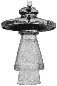 |
| Fig. 1. Standard Type of Locke High-Tension Insulator. |
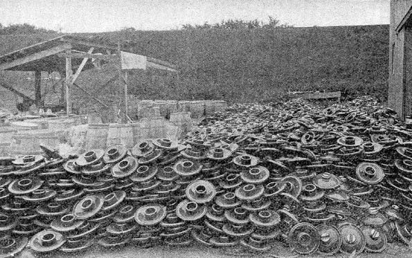
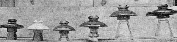
The type of insulator which is now being manufactured in this factory for the highest voltages is known as the Victor type of Locke insulators. This insulator is made in 20 styles, the general construction of which is with an eave-trough around the periphery of the insulator for carrying off rain water, though not all are made with this eave. Fig. 1 shows the standard type, of which 70,000 are now being manufactured for immediate application on various power transmission lines. Fig. 2 is of interest as showing a pile of 20,000 of these large insulators. This insulator is glazed around with a long glass centre, and is 10-1/2 inches in diameter, 11 inches high, weighs 12 pounds, and is capable of withstanding a pressure of 60,000 volts; each insulator, however, is given a salt water test of 120,000 volts. The leakage at 60,000 volts is said to be less than one watt, and at 50,000 volts the leakage is about one-eighth of one watt. Fig. 3 shows six of the 20 types of this insulator. The principle of construction of each will be easily understood by noting the contour, and that some are with glass bases and others with porcelain.
| |||
| Fig. 2. A Pile of 20,000 Insulators Weighing 12 Pounds Each. |
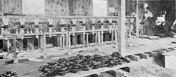
An interesting step in the production of these insulators is the method of testing. A Stanley generator of 8,000 and 16,000 alternations carries current to a low-tension transformer at 500 volts, and from this transformer the current is led into a high-tension transformer at 50 volts; it is here raised to 10,000 volts in each transformer. The equipment consists of three banks of transformers of four each and they are connected in series so as to develop 120,000 volts. One terminal is led to the metal cups which are filled with salt brine, and in which the head of the insulator is immersed. The other terminal is connected with steel rods, which are placed in the glass or porcelain centre. When the high-tension current is applied if there should be a defective insulator in the group it will immediately puncture a hole through the outer glazing, indicating the defect by a flash and sharp snap. This testing system is shown in Fig. 4. All the insulators produced in this factory are tested to double the line capacity for which they are intended.
| |||
| Fig. 3. Six Types of Locke High-Tension Insulators. |
| |||
| Fig. 4. Testing Department for Locke Insulators. |